Discussion:
MFJ-868 SWR/Wattmeter
(too old to reply)
Jim Higgins
2011-08-06 15:19:41 UTC
Permalink
Does anyone have a MFJ-868 SWR/Wattmeter?

Is it really a true peak reading meter?

Any other comments about it?
Owen Duffy
2011-08-06 22:01:04 UTC
Permalink
Post by Jim Higgins
Does anyone have a MFJ-868 SWR/Wattmeter?
MFJ claims that some of its products indicate PEP on SSB telephony, and
some of the claims are plainly fraud.

In my experience, if the instrument does not use an active 'sample and
hold' amplifier, it does not work adequately.

In the MFJ949E tuner, the PCB has provision for a single transistor
amplifier, which if fitted, works passably... but they do not populate
the board with the 20c worth of parts needed.

The good news is that the MFJ868 does have an active PEP amplifier, it
looks a similar circuit to that in my AL80B which does work quite well.
I have not checked the circuit in detail, nor the time constants
involved, but this has a chance of working and working well.
Post by Jim Higgins
Is it really a true peak reading meter?
Well, of the MFJ949E, MFJ says "Lets you easily read SWR, true peak
forward and average reflected power simultaneously on 300 Watt or 30
Watt ranges", and let me assure you that their "true peak forward" is a
fraud... so this claim questions MFJ's credibility.

Don't trust any advertising claim with the word "true" in it.

BTW, the reflected meter in the '949E does not read average power of SSB
telephony either, both meters can read the average power of an
unmodulated wave.

Sellers make extravagant claims to a tame market that mostly doesn't
understand the technical side.
Post by Jim Higgins
Any other comments about it?
None...


Owen
John S
2011-08-06 22:06:06 UTC
Permalink
Post by Owen Duffy
Post by Jim Higgins
Does anyone have a MFJ-868 SWR/Wattmeter?
MFJ claims that some of its products indicate PEP on SSB telephony, and
some of the claims are plainly fraud.
In my experience, if the instrument does not use an active 'sample and
hold' amplifier, it does not work adequately.
In the MFJ949E tuner, the PCB has provision for a single transistor
amplifier, which if fitted, works passably... but they do not populate
the board with the 20c worth of parts needed.
The good news is that the MFJ868 does have an active PEP amplifier, it
looks a similar circuit to that in my AL80B which does work quite well.
I have not checked the circuit in detail, nor the time constants
involved, but this has a chance of working and working well.
Post by Jim Higgins
Is it really a true peak reading meter?
Well, of the MFJ949E, MFJ says "Lets you easily read SWR, true peak
forward and average reflected power simultaneously on 300 Watt or 30
Watt ranges", and let me assure you that their "true peak forward" is a
fraud... so this claim questions MFJ's credibility.
Don't trust any advertising claim with the word "true" in it.
BTW, the reflected meter in the '949E does not read average power of SSB
telephony either, both meters can read the average power of an
unmodulated wave.
Sellers make extravagant claims to a tame market that mostly doesn't
understand the technical side.
Post by Jim Higgins
Any other comments about it?
None...
Owen
Excellent information, Owen. Thank you.

John S
BillyBobMarley
2011-08-28 00:33:47 UTC
Permalink
Post by John S
Post by Owen Duffy
Post by Jim Higgins
Does anyone have a MFJ-868 SWR/Wattmeter?
MFJ claims that some of its products indicate PEP on SSB telephony, and
some of the claims are plainly fraud.
In my experience, if the instrument does not use an active 'sample and
hold' amplifier, it does not work adequately.
In the MFJ949E tuner, the PCB has provision for a single transistor
amplifier, which if fitted, works passably... but they do not populate
the board with the 20c worth of parts needed.
The good news is that the MFJ868 does have an active PEP amplifier, it
looks a similar circuit to that in my AL80B which does work quite well.
I have not checked the circuit in detail, nor the time constants
involved, but this has a chance of working and working well.
Post by Jim Higgins
Is it really a true peak reading meter?
Well, of the MFJ949E, MFJ says "Lets you easily read SWR, true peak
forward and average reflected power simultaneously on 300 Watt or 30
Watt ranges", and let me assure you that their "true peak forward" is a
fraud... so this claim questions MFJ's credibility.
Don't trust any advertising claim with the word "true" in it.
BTW, the reflected meter in the '949E does not read average power of SSB
telephony either, both meters can read the average power of an
unmodulated wave.
Sellers make extravagant claims to a tame market that mostly doesn't
understand the technical side.
Post by Jim Higgins
Any other comments about it?
None...
Owen
Excellent information, Owen. Thank you.
John S
MFJ = Mighty Fine Junk
tom
2011-08-28 02:40:29 UTC
Permalink
Post by BillyBobMarley
MFJ = Mighty Fine Junk
If this is your opinion you can't evaluate hardware worth bleep.

The majority of what they sell does exactly what it's advertised to do.
You have to read the specs. And read the reviews carefully because
the hams who post that can't make the items work are often just ignorant
or incompetent.

It is not the best available, but it is often good enough.

tom
K0TAR
dave
2011-08-28 02:55:48 UTC
Permalink
Post by tom
Post by BillyBobMarley
MFJ = Mighty Fine Junk
If this is your opinion you can't evaluate hardware worth bleep.
The majority of what they sell does exactly what it's advertised to do.
You have to read the specs. And read the reviews carefully because
the hams who post that can't make the items work are often just ignorant
or incompetent.
It is not the best available, but it is often good enough.
tom
K0TAR
You can call them up and complain directly to the designers. Try doing
that with Rohde and Scrwarz.
Jeff Liebermann
2011-08-28 04:22:32 UTC
Permalink
Post by tom
The majority of what they sell does exactly what it's advertised to do.
You have to read the specs.
Generally true. However, I spent some time modeling the MFJ-1800
2.4GHz antenna and came the conclusion that it's not even close to 50
ohms and more like 300 ohms. I guess they forgot to include a balun:
<http://www.mfjenterprises.com/Product.php?productid=MFJ-1800>
<http://802.11junk.com/jeffl/antennas/mfj1800/index.html>
While one screwup is not sufficient to claim that the entire product
line is lacking, it does make me very suspicious and wary.
Post by tom
And read the reviews carefully because
the hams who post that can't make the items work are often just ignorant
or incompetent.
True. Everyone that disagrees with me is automatically judged to be
incompetent, ignorant, or both.

MFJ-868 shows 21 reviews, most of them positive.
<http://www.eham.net/reviews/detail/6459>
The ones with critical reviews were either failures of some manner, or
what I attribute to calibration issues. Looking at the schematic at:
<http://www.mfjenterprises.com/pdffiles/MFJ-868.pdf>
methinks it's "good enough". I'm not thrilled by the design, but it
does have an integrating RC networks, with a 2 second time constant,
which would make it peak reading.

QST compares various wattmeters:
<http://www.palstar.com/qstWM150.pdf>
Unfortunately, the MJF-868 is not reviewed, but the article might
offer some clues as to what to look for in a wattmeter.
--
Jeff Liebermann ***@cruzio.com
150 Felker St #D http://www.LearnByDestroying.com
Santa Cruz CA 95060 http://802.11junk.com
Skype: JeffLiebermann AE6KS 831-336-2558
unknown
2011-08-28 14:14:06 UTC
Permalink
Post by Jeff Liebermann
Post by tom
The majority of what they sell does exactly what it's advertised to do.
You have to read the specs.
Generally true. However, I spent some time modeling the MFJ-1800
2.4GHz antenna and came the conclusion that it's not even close to 50
<http://www.mfjenterprises.com/Product.php?productid=MFJ-1800>
<http://802.11junk.com/jeffl/antennas/mfj1800/index.html>
While one screwup is not sufficient to claim that the entire product
line is lacking, it does make me very suspicious and wary.
I'm curious, did you do any measurement and testing with an analyzer, etc., or
are all the figures simply calculated estimates?

Has anyone confirmed what the piece is that connects the driven element with the
coax connector that looks to be a short piece of coax covered in heat shrink?
Has anything been found or measured hiding under the heat shrink?

I realize we can all assume the antenna impedance is 50 ohms, but is it actually
stated in any of the specifications from MFJ? I didn't see any mention of
impedance specification at all for this antenna, but I could only find
information on the web page at the link you provided as well as in the pdf file
of the instructions for the MFJ-1800. The instructions are rather sparse.

Thanks for taking the time to provide details.

BTW, Irene's knocking at the door!

73, Renee
Jeff Liebermann
2011-08-28 18:33:10 UTC
Permalink
Post by unknown
Post by Jeff Liebermann
Post by tom
The majority of what they sell does exactly what it's advertised to do.
You have to read the specs.
Generally true. However, I spent some time modeling the MFJ-1800
2.4GHz antenna and came the conclusion that it's not even close to 50
<http://www.mfjenterprises.com/Product.php?productid=MFJ-1800>
<http://802.11junk.com/jeffl/antennas/mfj1800/index.html>
While one screwup is not sufficient to claim that the entire product
line is lacking, it does make me very suspicious and wary.
I'm curious, did you do any measurement and testing with an analyzer, etc., or
are all the figures simply calculated estimates?
There are no affordable "analyzers" that work at 2.4Ghz. I also have
not owned, or plan to own an MFJ-1800 antenna. The physical
measurements were done by a friend that owns this antenna and was
wondering why it didn't provide anywhere near the gain promised (as
compared to a commercial panel antenna).

Incidentally, I recently purchased a pair of totally misdesigned
2.4Ghz yagi's on eBay for about $8/ea.
<Loading Image...>
Note the crude driven element, exposed coax conductors, and lack of a
balun. What happened was that this was a cheap clone of another
similar antenna, which did provide all the required matching
circuitry. This vendor decided it was too much trouble to copy the
matching network and balun, so he just left it out. It has more gain
to the sides of the yagi, than in front.
Post by unknown
Has anyone confirmed what the piece is that connects the driven element with the
coax connector that looks to be a short piece of coax covered in heat shrink?
Has anything been found or measured hiding under the heat shrink?
There's a ferrite bead under the shrink tube. If you can find a
ferrite material that actually works at 2.4GHz, it might pretend to do
something useful. However, no way is it going to provide a 4:1
impedance transformation.
Post by unknown
I realize we can all assume the antenna impedance is 50 ohms, but is it actually
stated in any of the specifications from MFJ? I didn't see any mention of
impedance specification at all for this antenna, but I could only find
information on the web page at the link you provided as well as in the pdf file
of the instructions for the MFJ-1800. The instructions are rather sparse.
Good point. One can assume that if it uses a 50 ohm coax pigtail, a
50 ohm N connector, and is designed to connect to a wireless device
that presents 50 ohms, it just might need to be a 50 ohm antenna.
Post by unknown
Thanks for taking the time to provide details.
Yeah, I've done dumber things. There were several long discussion on
the topic in various newsgroups. The discussions inspired my burning
several evenings modeling the antenna:
<http://groups.google.com/group/alt.internet.wireless/browse_thread/thread/c891c0060ec92257/>
<http://groups.google.com/group/rec.radio.amateur.antenna/browse_thread/thread/e8990622c76c70b1/>
<http://groups.google.com/group/alt.internet.wireless/browse_thread/thread/57bb73ab886901b0/>
Post by unknown
BTW, Irene's knocking at the door!
Oh-oh.
Post by unknown
73, Renee
--
Jeff Liebermann ***@cruzio.com
150 Felker St #D http://www.LearnByDestroying.com
Santa Cruz CA 95060 http://802.11junk.com
Skype: JeffLiebermann AE6KS 831-336-2558
dave
2011-08-28 21:44:16 UTC
Permalink
Post by Jeff Liebermann
Post by unknown
I'm curious, did you do any measurement and testing with an analyzer, etc., or
are all the figures simply calculated estimates?
There are no affordable "analyzers" that work at 2.4Ghz. I also have
not owned, or plan to own an MFJ-1800 antenna. The physical
measurements were done by a friend that owns this antenna and was
wondering why it didn't provide anywhere near the gain promised (as
compared to a commercial panel antenna).
Incidentally, I recently purchased a pair of totally misdesigned
2.4Ghz yagi's on eBay for about $8/ea.
<http://802.11junk.com/jeffl/crud/wi-fi-yagi-that-sucks.jpg>
Note the crude driven element, exposed coax conductors, and lack of a
balun. What happened was that this was a cheap clone of another
similar antenna, which did provide all the required matching
circuitry. This vendor decided it was too much trouble to copy the
matching network and balun, so he just left it out. It has more gain
to the sides of the yagi, than in front.
You can make a killer wifi antenna out of a tin can and an N connector
you know...
Jeff Liebermann
2011-08-28 23:34:50 UTC
Permalink
Post by dave
You can make a killer wifi antenna out of a tin can and an N connector
you know...
A tin can is too small. I think you mean a coffee can.
In my never humble opinion, the cantenna sucks, but works tolerably
well for illuminating a parabolic dish.

Here's a model of the common coffee can antenna.
<http://802.11junk.com/jeffl/antennas/coffee2400/>
Notice the boresight error caused by the off center probe feed. 9.8dBi
gain, but there's a problem with my model somewhere. The average gain
test shows 1.54 indicating that the calculated gain is 1.88dB too
optimistic. The real gain is more like 8dBi. I can do that with a
biquad.

The cantenna also has a problem with calculating the probe feed
length. Where do you measure to? Starting from the tip, do you
measure to where the insulation stops on the N connector? To the
metal sleeve around the insulation? To the N connector base? Or
perhaps to the tin can itself? The error is not trivial. 1/4 wave at
the band edges are 3.02cm and 3.12cm. Assuming you want to land
somewhere between these limits, the cut error is:
3.12cm - 3.02cm = 0.10cm = +/-0.5mm
That's also possibly one of the reasons the original designer used a
conical probe feed. More bandwidth means any error has a smaller
effect.

I won't mention that the bottom of the can is rarely flat, making that
distance also a bit tricky to get right. Never mind that there's way
to adjust anything other than the length of the wire probe and it's
bend angle.

About 3 years ago, I was blessed with a friend who built about 6
assorted cantennas, but had no reliable way to tune or test them. I
stupidly volunteered. Most of them were resonant at about 1.8GHz.
Chop, cut, hack, solder, and they're now on 2.4Ghz. Measuring the
gain, none of them came close to what was expected. My indoor antenna
test range leaves much to be desired, but my transfer standard antenna
is accurate to +/-0.5dB gain.

The reason that the cantenna is such a "killer" antenna is that
literally *ANY* external antenna is an improvement over the stock
chip, PIFA, or rubber ducky collinear antenna found in most Wi-Fi
contrivances. You can even build one incorrectly and it will work
better than the stock antenna. For your amusement, here's a proper
biquad:
<http://802.11junk.com/jeffl/antennas/Biquad/index.html>
and by the way far too many web pages suggest it should be built:
<http://802.11junk.com/jeffl/antennas/biquad-junk/index.html>
The good antenna has a 50 ohm coax feed between the reflector and the
bow tie. The loser has a pair of wires, at some unknown impedance, in
the same place. Amazingly, it has almost the same gain, despite the
high VSWR.

Killer antenna, my posterior...
--
Jeff Liebermann ***@cruzio.com
150 Felker St #D http://www.LearnByDestroying.com
Santa Cruz CA 95060 http://802.11junk.com
Skype: JeffLiebermann AE6KS 831-336-2558
Jeff Liebermann
2011-08-28 23:52:07 UTC
Permalink
Post by Jeff Liebermann
Here's a model of the common coffee can antenna.
<http://802.11junk.com/jeffl/antennas/coffee2400/>
Incidentally, I once scribbled a spreadsheet that allegedly generates
an NEC2 card for a cantenna, given the can dimensions.
<http://802.11junk.com/jeffl/rf-calc/Coffee-can05.xls>
In theory, you should be able to cut-n-paste the section in blue, save
it as filename.nec, and feed it to 4NEC2 as can feed. It was
originally intended for parabolic dish feeds, but can be used for a
stand alone wi-fi antenna. Unfortunately, it's not ready for prime
time and has some errors. It's been so long since I threw it
together, that I don't even remember what was broken. Caveat Emptor.
--
Jeff Liebermann ***@cruzio.com
150 Felker St #D http://www.LearnByDestroying.com
Santa Cruz CA 95060 http://802.11junk.com
Skype: JeffLiebermann AE6KS 831-336-2558
dave
2011-08-29 00:47:52 UTC
Permalink
Post by Jeff Liebermann
Here's a model of the common coffee can antenna.
<http://802.11junk.com/jeffl/antennas/coffee2400/>
Incidentally, I once scribbled a spreadsheet that allegedly generates
an NEC2 card for a cantenna, given the can dimensions.
<http://802.11junk.com/jeffl/rf-calc/Coffee-can05.xls>
In theory, you should be able to cut-n-paste the section in blue, save
it as filename.nec, and feed it to 4NEC2 as can feed. It was
originally intended for parabolic dish feeds, but can be used for a
stand alone wi-fi antenna. Unfortunately, it's not ready for prime
time and has some errors. It's been so long since I threw it
together, that I don't even remember what was broken. Caveat Emptor.
Apparently you did your own homework. I use the 3gstore near Chicago.
They have a wifi dxers message board.
dave
2011-08-29 00:46:24 UTC
Permalink
Post by Jeff Liebermann
Post by dave
You can make a killer wifi antenna out of a tin can and an N connector
you know...
A tin can is too small. I think you mean a coffee can.
In my never humble opinion, the cantenna sucks, but works tolerably
well for illuminating a parabolic dish.
Here's a model of the common coffee can antenna.
<http://802.11junk.com/jeffl/antennas/coffee2400/>
Notice the boresight error caused by the off center probe feed. 9.8dBi
gain, but there's a problem with my model somewhere. The average gain
test shows 1.54 indicating that the calculated gain is 1.88dB too
optimistic. The real gain is more like 8dBi. I can do that with a
biquad.
The cantenna also has a problem with calculating the probe feed
length. Where do you measure to? Starting from the tip, do you
measure to where the insulation stops on the N connector? To the
metal sleeve around the insulation? To the N connector base? Or
perhaps to the tin can itself? The error is not trivial. 1/4 wave at
the band edges are 3.02cm and 3.12cm. Assuming you want to land
3.12cm - 3.02cm = 0.10cm = +/-0.5mm
That's also possibly one of the reasons the original designer used a
conical probe feed. More bandwidth means any error has a smaller
effect.
I won't mention that the bottom of the can is rarely flat, making that
distance also a bit tricky to get right. Never mind that there's way
to adjust anything other than the length of the wire probe and it's
bend angle.
Somebody did your homework for you:

http://www.turnpoint.net/wireless/cantennahowto.html
Jeff Liebermann
2011-08-29 01:53:39 UTC
Permalink
Post by dave
http://www.turnpoint.net/wireless/cantennahowto.html
Nope. That's on how to build a cantenna. What I'm doing is taking a
given size can, and generating an NEC2 deck suitable for modeling the
design. There's nothing on that web page about modeling. For that
matter, there are no test results and no cool looking plots. You
could build the cantenna according to the instructions, and never
really know what you've got, or what to expect.

Incidentally, I like the various photos of testing the cantenna on a
camera tripod. My guess is that the tripod is about 3ft off the
ground. Quiz: What's the maximum distance you can go at 2.4Ghz with
both ends 4ft off the ground, before the Fresnel Zone hits the ground?
<http://www.terabeam.com/support/calculations/fresnel-zone.php>
Plugging in various guess in the range, I get 0.025 miles or 132 ft.
Several of the antenna tests (can't find the link again) were longer.
Oh well.
--
Jeff Liebermann ***@cruzio.com
150 Felker St #D http://www.LearnByDestroying.com
Santa Cruz CA 95060 http://802.11junk.com
Skype: JeffLiebermann AE6KS 831-336-2558
Richard Clark
2011-08-29 02:23:01 UTC
Permalink
Post by Jeff Liebermann
You
could build the cantenna according to the instructions, and never
really know what you've got, or what to expect.
Looking at the bare can with probe feed, I would expect a horrible
launch characteristic at the lip without a flared end.

Perhaps some of your modeling suggests this.

73's
Richard Clark, KB7QHC
Jeff Liebermann
2011-08-29 04:24:17 UTC
Permalink
Post by Richard Clark
Post by Jeff Liebermann
You
could build the cantenna according to the instructions, and never
really know what you've got, or what to expect.
Looking at the bare can with probe feed, I would expect a horrible
launch characteristic at the lip without a flared end.
Perhaps some of your modeling suggests this.
The model is at:
<http://802.11junk.com/jeffl/antennas/coffee2400/index.html>
Note the 5 degree boresight error at:
<http://802.11junk.com/jeffl/antennas/coffee2400/slides/horiz-01.html>
That's not too horrible considering the 65 degree -3dB beamwidth.

I've seen several antenna with proper launchers. Here's one:
<http://www.seattlewireless.net/CookieCantenna>
The funnel will add about 4-5dB of gain depending on size. That begs
the question whether it would be easier to just built a horn antenna
and be done with it. The horn has more gain, easier to build, flat
surface for easier connector mounting, tunable back end of waveguide,
and potentially more portable:
<http://www.wired.com/culture/lifestyle/multimedia/2004/08/64440>
<http://www.brest-wireless.net/gallery/AntenneCornet>
<http://www.seattlewireless.net/CardboardHorn>

Also, I forgot to mumble something about the N connector mounting
screws and nuts projecting into the waveguide. Not a good idea as
those will have some effect. The screw heads should be on the inside
of the can, with the nuts and uncut threads on the outside. It will
look horrible but it will work better. Copper pop-rivets would
probably be best.
--
Jeff Liebermann ***@cruzio.com
150 Felker St #D http://www.LearnByDestroying.com
Santa Cruz CA 95060 http://802.11junk.com
Skype: JeffLiebermann AE6KS 831-336-2558
Sal
2011-08-29 05:55:22 UTC
Permalink
Post by Jeff Liebermann
Post by dave
You can make a killer wifi antenna out of a tin can and an N connector
you know...
A tin can is too small. I think you mean a coffee can.
In my never humble opinion, the cantenna sucks, but works tolerably
well for illuminating a parabolic dish.
I have a 2.4 GHz TV downconverter built into a coffee can. It was
tough to get a good picture, so I made a horn for it, using hardware
cloth. The horn is about three feet long and about three feet across
at the open end. I never made any quantitative measurements of the
increased signal at Channel 3 (the nominal output) but the reduction
in snow was considerable.
Jim Lux
2011-08-29 17:23:48 UTC
Permalink
Post by Jeff Liebermann
Post by unknown
Post by Jeff Liebermann
Post by tom
The majority of what they sell does exactly what it's advertised to do.
You have to read the specs.
Generally true. However, I spent some time modeling the MFJ-1800
2.4GHz antenna and came the conclusion that it's not even close to 50
<http://www.mfjenterprises.com/Product.php?productid=MFJ-1800>
<http://802.11junk.com/jeffl/antennas/mfj1800/index.html>
While one screwup is not sufficient to claim that the entire product
line is lacking, it does make me very suspicious and wary.
I'm curious, did you do any measurement and testing with an analyzer, etc., or
are all the figures simply calculated estimates?
There are no affordable "analyzers" that work at 2.4Ghz. I also have
not owned, or plan to own an MFJ-1800 antenna. The physical
measurements were done by a friend that owns this antenna and was
wondering why it didn't provide anywhere near the gain promised (as
compared to a commercial panel antenna).
Hmmm.. while you might not be able to buy an analyzer, that doesn't mean
that you couldn't have done the measurement by other means. A power
meter (perhaps an eval board for one of the analog devices parts)?
Maybe even using a WiFi card as a field strength meter at a little
distance away, and then using an adjustable stub tuner (e.g.
microstripline on a PC board. (or one of those "check your microwave
oven for leakage" meters from radio shack)

Sure, it's not as nice as that VNA from Anritsu or Agilent, but people
have been making microwave impedance measurements for decades with
pretty primitive gear.

Building a directional coupler in microstripline is a cookbook endeavor.
An hour with some copper clad board and a razor blade would do. If
you happen to have some copper foil tape around, it's even easier.

An impedance measuring system along the lines of the "3 meter" technique
(where you have a known L or C in series) is a possibility.

Not to mention that there are a lot of folks on this list who DO have
access to suitable analyzers.

So Renee's question was pretty reasonable.
Post by Jeff Liebermann
Incidentally, I recently purchased a pair of totally misdesigned
2.4Ghz yagi's on eBay for about $8/ea.
<http://802.11junk.com/jeffl/crud/wi-fi-yagi-that-sucks.jpg>
Note the crude driven element, exposed coax conductors, and lack of a
balun. What happened was that this was a cheap clone of another
similar antenna, which did provide all the required matching
circuitry. This vendor decided it was too much trouble to copy the
matching network and balun, so he just left it out. It has more gain
to the sides of the yagi, than in front.
Fascinating... especially since the matching network wouldn't normally
have any effect on the pattern. Balun/Choke having an effect, I could
see (coupling to the feedline screws up the pattern).
Post by Jeff Liebermann
Post by unknown
Has anyone confirmed what the piece is that connects the driven element with the
coax connector that looks to be a short piece of coax covered in heat shrink?
Has anything been found or measured hiding under the heat shrink?
There's a ferrite bead under the shrink tube. If you can find a
ferrite material that actually works at 2.4GHz, it might pretend to do
something useful. However, no way is it going to provide a 4:1
impedance transformation.
2.4 GHz is 12 cm wavelength

4-6cm of transmission line is a good fraction of a wavelength. How do
you know it's not 3/4 lambda of 75 or 92 ohm line, or something like
that. (1/4 wavelength of 75 ohms would transform 200 ohms to about 30
ohms, for instance)

I've worked with enough UHF and microwave antennas with weird funky
feedpoint things to not trust in first impressions. There could be all
sorts of parasitics that help the situation out, and they're tough to
model accurately (you're certainly not going to do it with NEC, for
instance.. I'd trust NEC for the feedpoint impedance without
matching/balun/stubs..)


Yeah, it's probably not a nice 1:1 match over the entire band, but then,
most antennas aren't. It just has to be "good enough" and in that
business, the loss in the feedline probably dominates anyway. Figure 3
dB of loss in the feedline, and you get a 6B improvement in return loss.


The model you have shows a beamwidth around 30 degrees (H) and 28
degrees (V).. that's a directivity around 16 dBi

4NEC2 is giving you 14dB gain.. that's moderately consistent, although 2
dB is something I'd want to figure why the difference. I'd want to
figure out why 2dB different, especially since you didn't put resistive
loading into your model, which, at 2.4GHz *will* make the match better

MFJ claims 15dBi, and that is also consistent with your model and the
back of the envelope from the pattern.
Post by Jeff Liebermann
Post by unknown
I realize we can all assume the antenna impedance is 50 ohms, but is it actually
stated in any of the specifications from MFJ? I didn't see any mention of
impedance specification at all for this antenna, but I could only find
information on the web page at the link you provided as well as in the pdf file
of the instructions for the MFJ-1800. The instructions are rather sparse.
Good point. One can assume that if it uses a 50 ohm coax pigtail, a
50 ohm N connector, and is designed to connect to a wireless device
that presents 50 ohms, it just might need to be a 50 ohm antenna.
Nope.. not if the feedline is a couple dB loss (which wouldn't be
unusual for a laptop pigtail using RG-174 or smaller).. All they really
care about in this kind of application is the directivity.

After all, how many ham antennas for HF have a PL-259/SO-239 "UHF"
connector on them. I wouldn't take the fact that it has a 50 ohm
connector as indicating anything other than it's a common connector that
people are likely to have mating connectors for.

75 ohm BNC, Ns, etc exist, but how many people use them on dipoles
(which have 72 ohm impedance)... nahh. they just use a 50 ohm cable, UHF
connectors, and are done with it.

If they used 75 ohm coax on this antenna, and it's close to a multiple
of 1/4 wavelength, then the match at the N connector is probably not a
lot worse than using 50 ohm coax on a dipole.
Jeff Liebermann
2011-08-30 00:50:01 UTC
Permalink
Post by Jim Lux
Post by Jeff Liebermann
Post by unknown
I'm curious, did you do any measurement and testing with an analyzer, etc., or
are all the figures simply calculated estimates?
There are no affordable "analyzers" that work at 2.4Ghz. I also have
not owned, or plan to own an MFJ-1800 antenna. The physical
measurements were done by a friend that owns this antenna and was
wondering why it didn't provide anywhere near the gain promised (as
compared to a commercial panel antenna).
Hmmm.. while you might not be able to buy an analyzer, that doesn't mean
that you couldn't have done the measurement by other means.
Well, not having the antenna prevented me from doing much. If I had
the antenna, I would have connected it to a home made reflection
coefficient bridge and my Wiltron 610D sweeper. I also have some
directional couplers, but all my detectors are currently blown.
<http://802.11junk.com/jeffl/pics/home/slides/BL-shop6.html>
(Right now, there's a chain saw torn apart on the bench). Either
bridge or coupler would have shown high VSWR for the antenna.

Incidentally, I don't consider it my job to supply test data for MFJ.
MFJ should run the tests and post both the procedures and test
results.

While it's a good thing to verify models with actual measurements, in
this case, just creating the model burned all my spare time for about
a week. I don't think I would have had time to do anything more than
a rough sanity check type of test.
Post by Jim Lux
A power
meter (perhaps an eval board for one of the analog devices parts)?
Maybe even using a WiFi card as a field strength meter at a little
distance away, and then using an adjustable stub tuner (e.g.
microstripline on a PC board. (or one of those "check your microwave
oven for leakage" meters from radio shack)
I have several microwave oven testers. They will barely detect RF
from an access point. Basically, they're just a diode detector, with
no RF gain. I wouldn't expect much from them:
<http://802.11junk.com/jeffl/pics/Microwave%20Leakage%20Detector/>
The detector diode is on the far left.

I do have an indoor antenna range of sorts. It's full of reflections,
but is good enough for measuring gain using a reference antenna. In
this case, I had a patch antenna and a biquad antenna tested in an
anechoic chamber and obtained fairly accurate gain curves. My guess
is that I can measure gain at 2.4Ghz to +/-2dB. Not great, but better
than guesswork.
Post by Jim Lux
Sure, it's not as nice as that VNA from Anritsu or Agilent, but people
have been making microwave impedance measurements for decades with
pretty primitive gear.
I still have several slotted lines buried somewhere.
Post by Jim Lux
Building a directional coupler in microstripline is a cookbook endeavor.
An hour with some copper clad board and a razor blade would do. If
you happen to have some copper foil tape around, it's even easier.
Yep, I've done that. On a good day, I'll get 20dB directivity, which
isn't so great.
<http://www.qsl.net/n9zia/24swr/index.html>
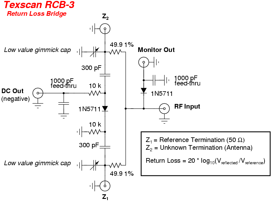
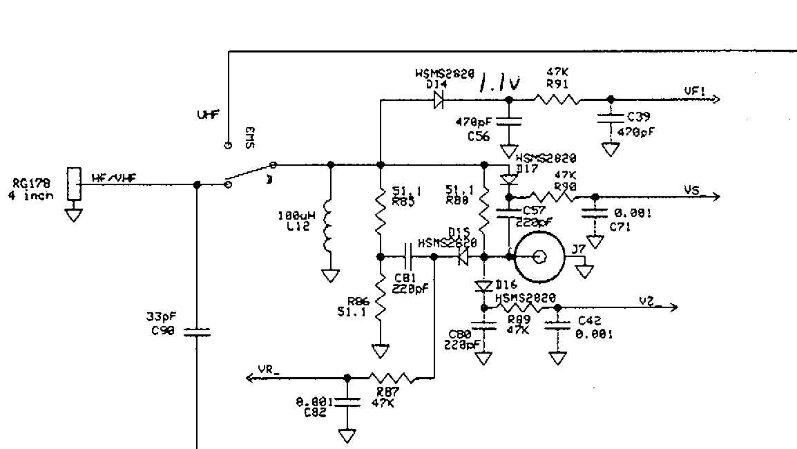
I prefer a reflection coefficient bridge, as in:
<http://pe2er.nl/wifiswr/>
I've built several of these. It won't tell you whether the antenna is
inductive or cazapitive, but will supply the VSWR (actually, the
reflection coefficient).
Post by Jim Lux
An impedance measuring system along the lines of the "3 meter" technique
(where you have a known L or C in series) is a possibility.
Pardon my ignorance, but what's that?
Post by Jim Lux
Not to mention that there are a lot of folks on this list who DO have
access to suitable analyzers.
Great. Let them borrow and MFJ-1800 antenna and run their own tests.
Post by Jim Lux
So Renee's question was pretty reasonable.
True. I should have tested my model to verify my allegations. Perhaps
I should also do indoor/outdoor tests, in various environmental
situations, in the presence of interference, and with a side by side
comparison with other antennas. Yeah, that would be great, but I
don't have that much time (or money). I threw together an NEC2 model
that suggested that the antenna is mis-designed and left it there.
Post by Jim Lux
Post by Jeff Liebermann
Incidentally, I recently purchased a pair of totally misdesigned
2.4Ghz yagi's on eBay for about $8/ea.
<http://802.11junk.com/jeffl/crud/wi-fi-yagi-that-sucks.jpg>
Note the crude driven element, exposed coax conductors, and lack of a
balun. What happened was that this was a cheap clone of another
similar antenna, which did provide all the required matching
circuitry. This vendor decided it was too much trouble to copy the
matching network and balun, so he just left it out. It has more gain
to the sides of the yagi, than in front.
Fascinating... especially since the matching network wouldn't normally
have any effect on the pattern. Balun/Choke having an effect, I could
see (coupling to the feedline screws up the pattern).
I didn't include the feedline in my model, which due to the lack of a
balun (I don't consider the ferrite bead to be a balun due to the high
frequency) will radiate and produce weird patterns. Never mind the
fairly large lengths of exposed conductors at both ends of the coax
cable. I'm not sure exactly what a 200 ohm antenna in a 50 ohm system
will do. 300 ohms in a 50 ohm system is a 6:1 VSWR and a 3.1 dB
mismatch loss. So what if we loose half the power in the mismatch.
Post by Jim Lux
Post by Jeff Liebermann
Post by unknown
Has anyone confirmed what the piece is that connects the driven element with the
coax connector that looks to be a short piece of coax covered in heat shrink?
Has anything been found or measured hiding under the heat shrink?
There's a ferrite bead under the shrink tube. If you can find a
ferrite material that actually works at 2.4GHz, it might pretend to do
something useful. However, no way is it going to provide a 4:1
impedance transformation.
2.4 GHz is 12 cm wavelength
4-6cm of transmission line is a good fraction of a wavelength. How do
you know it's not 3/4 lambda of 75 or 92 ohm line, or something like
that. (1/4 wavelength of 75 ohms would transform 200 ohms to about 30
ohms, for instance)
The owner of the antenna measured the coax cable dimensions. From
that, we determined that it was 50 ohms coax. I have the numbers
buried in email correspondence somewhere. I'll see if I can find
them. Digging.... Nothing yet, but I did find one more photo:
<http://802.11junk.com/jeffl/MFJ-1800/>
While it's difficult to transfer dimensions from the photos, the coax
cable even looks like a 50 ohm cable. Not the thick center conductor,
which makes 92 ohms improbable, and 75 ohms unlikely. You can see the
ferrite beads through the stink tube.
Post by Jim Lux
I've worked with enough UHF and microwave antennas with weird funky
feedpoint things to not trust in first impressions. There could be all
sorts of parasitics that help the situation out, and they're tough to
model accurately (you're certainly not going to do it with NEC, for
instance.. I'd trust NEC for the feedpoint impedance without
matching/balun/stubs..)
Well, that's what my model did. The characteristic impedance of the
model is set to 200 ohms at the folded dipole. No matching network
involved. See:
<http://802.11junk.com/jeffl/antennas/mfj1800/slides/VSWR.html>
and note the 200 ohms in the upper left of the VSWR graph.
Post by Jim Lux
Yeah, it's probably not a nice 1:1 match over the entire band, but then,
most antennas aren't.
Look again at the graphs.
<http://802.11junk.com/jeffl/antennas/mfj1800/slides/VSWR.html>
It's absolutely gorgeous across the band. Less than 1.3:1 from 2400
to 2483.5. I would also have expected a much more narrow band antenna
and was very surprised at the wide bandwidth. That's not normal for a
high gain yagi.
Post by Jim Lux
It just has to be "good enough" and in that
business, the loss in the feedline probably dominates anyway. Figure 3
dB of loss in the feedline, and you get a 6B improvement in return loss.
Yep. That's why I measure VSWR at the antenna, not the source. I
like to use LMR-400 with 6.6dB loss per 100ft. 3dB loss would be
about 50 ft of coax cable, which is MUCH longer than I would use at
2.4GHz. Also, I'm partial to putting the radio next to the antenna,
which reduces coax losses to nearly zero.
Post by Jim Lux
The model you have shows a beamwidth around 30 degrees (H) and 28
degrees (V).. that's a directivity around 16 dBi
Yep. For the benefit of those trying to follow all this, see the
numbers in red at the right:
<http://802.11junk.com/jeffl/antennas/mfj1800/slides/Horiz.html>
Incidentally, notice the asymmetrical pattern, caused by the off
center line position of the copper folded dipole driven element.
Post by Jim Lux
4NEC2 is giving you 14dB gain.. that's moderately consistent, although 2
dB is something I'd want to figure why the difference.
The 2dB is from the -2dB gain in the reverse direction (180 deg).
14dB forward gain. -2dB reverse gain. 14 - (-2) = 16dB directivity.
I don't see a problem.
Post by Jim Lux
I'd want to
figure out why 2dB different, especially since you didn't put resistive
loading into your model, which, at 2.4GHz *will* make the match better
Ummm... why would I need a load? I'm only interested in what the
antenna looks like to whatever I connect to the terminals. If I
included the generator source impedance in the model, I would have to
also include the generator output impedance characteristics,
connecting cables, and possibly some manner of 4:1 xformer.
Post by Jim Lux
MFJ claims 15dBi, and that is also consistent with your model and the
back of the envelope from the pattern.
Close enough. When in doubt, always round up to make the numbers look
better.
Post by Jim Lux
Post by Jeff Liebermann
Post by unknown
I realize we can all assume the antenna impedance is 50 ohms, but is it actually
stated in any of the specifications from MFJ? I didn't see any mention of
impedance specification at all for this antenna, but I could only find
information on the web page at the link you provided as well as in the pdf file
of the instructions for the MFJ-1800. The instructions are rather sparse.
Good point. One can assume that if it uses a 50 ohm coax pigtail, a
50 ohm N connector, and is designed to connect to a wireless device
that presents 50 ohms, it just might need to be a 50 ohm antenna.
Nope.. not if the feedline is a couple dB loss (which wouldn't be
unusual for a laptop pigtail using RG-174 or smaller).. All they really
care about in this kind of application is the directivity.
Maybe. Using coax loss to improve VSWR is an old trick. Whether it's
being done intentionally is debatable. I prefer to assume that if all
the major components are 50 ohms, then perhaps the antenna should also
be 50 ohms.
Post by Jim Lux
After all, how many ham antennas for HF have a PL-259/SO-239 "UHF"
connector on them.
Too many. However, HF antennas are not as critical to construction
and component differences as microwave antennas. What hams get away
with building HF antennas, would be doom and disaster at microwave
frequencies. You also don't see UHF connectors and banana jacks at
UHF frequencies.
Post by Jim Lux
I wouldn't take the fact that it has a 50 ohm
connector as indicating anything other than it's a common connector that
people are likely to have mating connectors for.
Ok, I'll conceded that there's a possibility that there's some
matching magic going on behind the curtains, that's not visible to
mere mortals. Lacking the necessary insight, I prefer to judge based
on what I can see, feel, touch, understand, and test.
Post by Jim Lux
75 ohm BNC, Ns, etc exist, but how many people use them on dipoles
(which have 72 ohm impedance)... nahh. they just use a 50 ohm cable, UHF
connectors, and are done with it.
Most of the feed lines to my roof are 75 ohm CATV rigid cable. Also,
plenty of 75 ohm RG-6a/u. Worst case VSWR for doing this is 1.5:1.
The tiny mismatch loss for this arrangement is more than compensated
for the lower coax loss of 75 ohm coax, compared to similar sized 50
ohm coax.
<http://www.qsl.net/n9zia/wireless/75_ohm_hardline.html>
Post by Jim Lux
If they used 75 ohm coax on this antenna, and it's close to a multiple
of 1/4 wavelength, then the match at the N connector is probably not a
lot worse than using 50 ohm coax on a dipole.
The antenna impedance (by my model) is between 200-300 ohms. To use a
1/4 wave section to match that to 50 ohms, the coax would need to be:
Zo = (Zout * Zin)^0.5
Zo = (200 * 50)^0.5 = 100 ohms
93 ohm RG-62/u would probably be close enough. However, the coax
cable in the photo is certainly not 93 ohms (judging by the fat center
conductor).
--
Jeff Liebermann ***@cruzio.com
150 Felker St #D http://www.LearnByDestroying.com
Santa Cruz CA 95060 http://802.11junk.com
Skype: JeffLiebermann AE6KS 831-336-2558
Jim Lux
2011-08-30 18:02:58 UTC
Permalink
Post by Jeff Liebermann
Well, not having the antenna prevented me from doing much.
True enough..
Post by Jeff Liebermann
Incidentally, I don't consider it my job to supply test data for MFJ.
MFJ should run the tests and post both the procedures and test
results.
Why should they bother. They have someone do a design that seems to work
acceptably well, and they sell it at a bargain price. You want
published test data and test procedures and it costs more. I'm sure the
Tessco catalog has something of comparable performance that comes with
test data (heck, you could have the mfr test the very serial number unit
they're shipping to you, for a price<grin>)
Post by Jeff Liebermann
Yep, I've done that. On a good day, I'll get 20dB directivity, which
isn't so great.
<http://www.qsl.net/n9zia/24swr/index.html>
but sufficient for measuring Z of an antenna, if that's the route you
want to go.
Post by Jeff Liebermann
<http://pe2er.nl/wifiswr/>
I've built several of these. It won't tell you whether the antenna is
inductive or cazapitive, but will supply the VSWR (actually, the
reflection coefficient).
Post by Jim Lux
An impedance measuring system along the lines of the "3 meter" technique
(where you have a known L or C in series) is a possibility.
Pardon my ignorance, but what's that?
More common in power electronics, but basically you put the UUT in
series with a known reactance and known resistance, and measure the
voltages across all three. Then you can solve for the resistance and
reactance of the unknown. Back in the day, this was solved graphically,
but these days, you can do with a spreadsheet or calculator. The trick
is that there are often 2 possible solutions, but usually, only one is
"reasonable".
Post by Jeff Liebermann
True. I should have tested my model to verify my allegations. Perhaps
I should also do indoor/outdoor tests, in various environmental
situations, in the presence of interference, and with a side by side
comparison with other antennas. Yeah, that would be great, but I
don't have that much time (or money). I threw together an NEC2 model
that suggested that the antenna is mis-designed and left it there.
I didn't include the feedline in my model, which due to the lack of a
balun (I don't consider the ferrite bead to be a balun due to the high
frequency) will radiate and produce weird patterns. Never mind the
fairly large lengths of exposed conductors at both ends of the coax
cable. I'm not sure exactly what a 200 ohm antenna in a 50 ohm system
will do. 300 ohms in a 50 ohm system is a 6:1 VSWR and a 3.1 dB
mismatch loss. So what if we loose half the power in the mismatch.
Yeah, but I'll bet the transmitter in a WiFi node doesn't have a
particularly good match either.. so you could come out better or worse.
3dB loss on top of 15dBi gain is still a net of 12dB over whatever
little antenna there was before (if it was even 0dBi)
Post by Jeff Liebermann
Post by Jim Lux
4-6cm of transmission line is a good fraction of a wavelength. How do
you know it's not 3/4 lambda of 75 or 92 ohm line, or something like
that. (1/4 wavelength of 75 ohms would transform 200 ohms to about 30
ohms, for instance)
The owner of the antenna measured the coax cable dimensions. From
that, we determined that it was 50 ohms coax.
OK.. then so much for that idea..
Post by Jeff Liebermann
Post by Jim Lux
I've worked with enough UHF and microwave antennas with weird funky
feedpoint things to not trust in first impressions. There could be all
sorts of parasitics that help the situation out, and they're tough to
model accurately (you're certainly not going to do it with NEC, for
instance.. I'd trust NEC for the feedpoint impedance without
matching/balun/stubs..)
Well, that's what my model did. The characteristic impedance of the
model is set to 200 ohms at the folded dipole. No matching network
<http://802.11junk.com/jeffl/antennas/mfj1800/slides/VSWR.html>
and note the 200 ohms in the upper left of the VSWR graph.
Post by Jim Lux
Yeah, it's probably not a nice 1:1 match over the entire band, but then,
most antennas aren't.
Look again at the graphs.
<http://802.11junk.com/jeffl/antennas/mfj1800/slides/VSWR.html>
It's absolutely gorgeous across the band. Less than 1.3:1 from 2400
to 2483.5. I would also have expected a much more narrow band antenna
and was very surprised at the wide bandwidth. That's not normal for a
high gain yagi.
well.. good match at 200 ohms... I was thinking 50 ohms, so it's equally
sucky over the entire band.

80 MHz out of 2400 is, what, about 3% BW? that's like 5MHz on a 2m antenna.

these sort of yagis actually are fairly broadband. Note that all the
directors are the same length, too. What they don't typically get is a
lot of gain for the length.
Post by Jeff Liebermann
Post by Jim Lux
It just has to be "good enough" and in that
business, the loss in the feedline probably dominates anyway. Figure 3
dB of loss in the feedline, and you get a 6B improvement in return loss.
Yep. That's why I measure VSWR at the antenna, not the source. I
like to use LMR-400 with 6.6dB loss per 100ft. 3dB loss would be
about 50 ft of coax cable, which is MUCH longer than I would use at
2.4GHz. Also, I'm partial to putting the radio next to the antenna,
which reduces coax losses to nearly zero.
yeah, but using LMR-400 with that $20 antenna wouldn't necessarily be
the expected application. It's sold as a "laptop range enhancer" for
the most part, and I'd expect 3-6 ft of some small (lossy) flexible
stuff. I'd worry about the LMR-400 bending the antenna.
Post by Jeff Liebermann
Post by Jim Lux
The model you have shows a beamwidth around 30 degrees (H) and 28
degrees (V).. that's a directivity around 16 dBi
Yep. For the benefit of those trying to follow all this, see the
<http://802.11junk.com/jeffl/antennas/mfj1800/slides/Horiz.html>
Incidentally, notice the asymmetrical pattern, caused by the off
center line position of the copper folded dipole driven element.
Post by Jim Lux
4NEC2 is giving you 14dB gain.. that's moderately consistent, although 2
dB is something I'd want to figure why the difference.
The 2dB is from the -2dB gain in the reverse direction (180 deg).
14dB forward gain. -2dB reverse gain. 14 - (-2) = 16dB directivity.
I don't see a problem.
Oh.. I didn't see that.. so the beamwidth and directivity are
consistent. Nice that back of the envelope estimation theory works.
Post by Jeff Liebermann
Post by Jim Lux
I'd want to
figure out why 2dB different, especially since you didn't put resistive
loading into your model, which, at 2.4GHz *will* make the match better
Ummm... why would I need a load? I'm only interested in what the
antenna looks like to whatever I connect to the terminals. If I
included the generator source impedance in the model, I would have to
also include the generator output impedance characteristics,
connecting cables, and possibly some manner of 4:1 xformer.
The elements are lossy, aren't they? That will improve the match (and
reduce the gain). Sort of the same idea as the Terminated folded
dipole.. add loss, improve match. And just like for that kind of
application, I think what they're selling here is "some gain, and some
directivity, at very low price"
Post by Jeff Liebermann
Post by Jim Lux
Post by Jeff Liebermann
Post by unknown
I realize we can all assume the antenna impedance is 50 ohms, but is it actually
stated in any of the specifications from MFJ? I didn't see any mention of
impedance specification at all for this antenna, but I could only find
information on the web page at the link you provided as well as in the pdf file
of the instructions for the MFJ-1800. The instructions are rather sparse.
Good point. One can assume that if it uses a 50 ohm coax pigtail, a
50 ohm N connector, and is designed to connect to a wireless device
that presents 50 ohms, it just might need to be a 50 ohm antenna.
Nope.. not if the feedline is a couple dB loss (which wouldn't be
unusual for a laptop pigtail using RG-174 or smaller).. All they really
care about in this kind of application is the directivity.
Maybe. Using coax loss to improve VSWR is an old trick. Whether it's
being done intentionally is debatable. I prefer to assume that if all
the major components are 50 ohms, then perhaps the antenna should also
be 50 ohms.
I wouldn't.. For that matter, the source impedance probably isn't 50
ohms in the box its connected to. Just looking over some MMIC data
sheets I have here, it looks like they have 2:1 as a worst case and
1.5:1 typical..

This kind of stuff isn't designed like high performance RF systems. They
pick the cheapest amplifier, often don't care much about DC power
efficiency, and cobble up some sort of output filter that keeps the
spurious down low enough to meet Part 15. It's not like specsheets for
consumer WiFi gear actually give you power "at the connector" or
radiated power. All they care is that they don't bust the FCC limits,
and not be "too low" that they'll get consumer complaints.
Post by Jeff Liebermann
Post by Jim Lux
I wouldn't take the fact that it has a 50 ohm
connector as indicating anything other than it's a common connector that
people are likely to have mating connectors for.
Ok, I'll conceded that there's a possibility that there's some
matching magic going on behind the curtains, that's not visible to
mere mortals. Lacking the necessary insight, I prefer to judge based
on what I can see, feel, touch, understand, and test.
No.. I think its not that they think they have a good match, I think
they just don't care, because in the application, it's "good enough".
They're not designing a deep space communication link where they have to
eke out every last hundredth of a dB to get that 10bps through.
Jeffrey Angus
2011-08-31 20:10:39 UTC
Permalink
Post by Jeff Liebermann
Incidentally, I don't consider it my job to supply test data for MFJ.
MFJ should run the tests and post both the procedures and test
results.
And the newest innovation in dish antennas...
<Loading Image...>

Jeff-1.0
wa6fwi
--
"Everything from Crackers to Coffins"
Jeff Liebermann
2011-09-01 03:21:19 UTC
Permalink
Post by Jeffrey Angus
And the newest innovation in dish antennas...
<http://thereifixedit.files.wordpress.com/2011/08/white-trash-repairs-seems-legit.jpg>
Jeff-1.0
wa6fwi
I like mine better:
<http://802.11junk.com/jeffl/antennas/Dish-wood/>
Just add aluminum foil and a feed.
--
# Jeff Liebermann 150 Felker St #D Santa Cruz CA 95060
# 831-336-2558
# http://802.11junk.com ***@cruzio.com
# http://www.LearnByDestroying.com AE6KS
amdx
2011-08-31 18:49:31 UTC
Permalink
Post by unknown
Post by Jeff Liebermann
Post by tom
The majority of what they sell does exactly what it's advertised to do.
You have to read the specs.
Generally true. However, I spent some time modeling the MFJ-1800
2.4GHz antenna and came the conclusion that it's not even close to 50
<http://www.mfjenterprises.com/Product.php?productid=MFJ-1800>
<http://802.11junk.com/jeffl/antennas/mfj1800/index.html>
While one screwup is not sufficient to claim that the entire product
line is lacking, it does make me very suspicious and wary.
I'm curious, did you do any measurement and testing with an analyzer, etc., or
are all the figures simply calculated estimates?
Has anyone confirmed what the piece is that connects the driven element with the
coax connector that looks to be a short piece of coax covered in heat shrink?
Has anything been found or measured hiding under the heat shrink?
The coax is RGS-303, 50 ohm coax. PTFE center insulator, FEP jacket.
http://wireandcable.thermaxcdt.com/item/high-performance-coaxial-cabl...
The coax has 4 toroids slid over it.
Mikek
unknown
2011-09-02 06:04:37 UTC
Permalink
Guys, guys, when I wrote asking what I thought were a couple of simple questions
just to clarify some points, I never thought it would end up creating such a
stir. Don't get me wrong, I am enjoying all the technical back and forth
communication, it's a whole lot more than I could have imagined.

I just wanted to pop in to say thanks to everyone while the thread is still
active. It's turning out to be quite educational, I really appreciate it. Now, I
am off to try to catch up with the latest replies.

73, Renee
amdx
2011-08-31 18:57:31 UTC
Permalink
Post by Jeff Liebermann
Post by tom
The majority of what they sell does exactly what it's advertised to do.
You have to read the specs.
Generally true. However, I spent some time modeling the MFJ-1800
2.4GHz antenna and came the conclusion that it's not even close to 50
<http://www.mfjenterprises.com/Product.php?productid=MFJ-1800>
<http://802.11junk.com/jeffl/antennas/mfj1800/index.html>
While one screwup is not sufficient to claim that the entire product
line is lacking, it does make me very suspicious and wary.
Hi Jeff,
I see MFJ now has a Bi-Quad 12dbi antenna.
http://www.mfjenterprises.com/Product.php?productid=MFJ-1804
If I send the the dimensions....
Just kidding!
Thanks for all the work.
Mikek
Jeff Liebermann
2011-09-01 03:55:57 UTC
Permalink
Post by amdx
Hi Jeff,
Likewise. alt.internet.wireless appears to be dead. Oh well.
Thanks for posting the info on the coax cable in the MFJ-1800. I
couldn't find the applicable message with Google Groups.
Post by amdx
I see MFJ now has a Bi-Quad 12dbi antenna.
http://www.mfjenterprises.com/Product.php?productid=MFJ-1804
If I send the the dimensions....
Ummm.... please don't do that.
Post by amdx
Just kidding!
Whew!

Interesting MFJ-1804 biquad antenna. In order to get 12dBi gain out
of something like that, it would either need to be 2 biquads and some
kind of power splitter, or one of those extended biquads as in:
<http://www.larsen-b.com/Article/201.html>
or the overkill version at:
<http://www.digdice.com/diy-wifi-antenna-double-dual-biquad-16-17-dbi/>
or maybe a biquad-yagi conglomeration:
<http://www.digdice.com/biquad-yagi-24ghz-antenna/>
Of course, MFJ supplies no specs, no manual, no dimensions, no test
results, no test procedures, no graphs, and no clue what's inside. For
$60, I would expect better, especially since I can buy something as
good or better for much less:
<http://www.l-com.com/item.aspx?id=21808> (3 element loop yagi)
<http://www.ebay.com/itm/170628411340> (4 element patch ant)

Looks like MFJ has a line of 2.4Ghz products, that don't seem to be
easily found on the product listing pull-down.
<http://www.mfjenterprises.com/Product.php?productid=MFJ-1800>
<http://www.mfjenterprises.com/Product.php?productid=MFJ-1801>
<http://www.mfjenterprises.com/Product.php?productid=MFJ-1802>
<http://www.mfjenterprises.com/Product.php?productid=MFJ-1804>
<http://www.mfjenterprises.com/Product.php?productid=MFJ-1805>
Post by amdx
Thanks for all the work.
Mikek
Y'er welcome.
--
# Jeff Liebermann 150 Felker St #D Santa Cruz CA 95060
# 831-336-2558
# http://802.11junk.com ***@cruzio.com
# http://www.LearnByDestroying.com AE6KS
amdx
2011-09-01 14:35:37 UTC
Permalink
Post by Jeff Liebermann
Post by amdx
Hi Jeff,
Likewise. alt.internet.wireless appears to be dead. Oh well.
Thanks for posting the info on the coax cable in the MFJ-1800. I
couldn't find the applicable message with Google Groups.
Post by amdx
I see MFJ now has a Bi-Quad 12dbi antenna.
http://www.mfjenterprises.com/Product.php?productid=MFJ-1804
If I send the the dimensions....
Ummm.... please don't do that.
Post by amdx
Just kidding!
Whew!
Interesting MFJ-1804 biquad antenna. In order to get 12dBi gain out
of something like that, it would either need to be 2 biquads and some
<http://www.larsen-b.com/Article/201.html>
Ya, I have my doubts about the 12 dbi gain figure. I have built a few
biquads, (with your feed point correction), it has amazed me how easy
it is to make them work (at 2.4 Ghz), I always thought the short
wavelength would cause many dimensional errors. Yes, they work, what
does "work" mean :-)
I've settled on a flat panel antenna for my boat antenna
(15dbi manu. spec.) At one time I had a dish with biquad feed, but it
was to tight, when the wind blew or tide changed it would miss the target.
Do you believe the 20 dbi figure?
http://www.ebay.com/itm/20-DBi-2-4GHz-Wifi-Yagi-Antenna-RP-SMA-Router-Wifi-/110730734175?_trksid=p4340.m1374&_trkparms=algo%3DPI.WATCH%26its%3DC%252BS%26itu%3DUCC%26otn%3D15%26ps%3D63%26clkid%3D2473925749399603295

Mikek
Jeff Liebermann
2011-09-01 17:11:52 UTC
Permalink
Post by amdx
Ya, I have my doubts about the 12 dbi gain figure.
Everyone lies about gain, but that's ok because few people can measure
the gain (and get reproducible results).
Post by amdx
I have built a few
biquads, (with your feed point correction), it has amazed me how easy
it is to make them work (at 2.4 Ghz), I always thought the short
wavelength would cause many dimensional errors. Yes, they work, what
does "work" mean :-)
For a given physical size antenna, high gain antennas imply narrow
bandwidth and critical construction. On the other foot, low gain
antennas, such as the biquad, is fairly broadband, and therefore not
particularly critical to construct. What's fun is to attach the
antenna to a reflection coefficient bridge or directional coupler,
<http://pe2er.nl/wifiswr/>
<Loading Image...>
<http://www.qsl.net/n9zia/rlb/>
sweep generator, and oscilloscope to look at the VSWR curve. Then try
moving things around. On my crowded workbench, location of the
antenna relative to the highly reflective test equipment make a huge
difference. The changes do not really have a big effect on antenna
operation, but they certainly present a different picture as compared
to the nice clean curves on the data sheets.
Post by amdx
Do you believe the 20 dbi figure?
http://www.ebay.com/itm/20-DBi-2-4GHz-Wifi-Yagi-Antenna-RP-SMA-Router-Wifi-/110730734175?_trksid=p4340.m1374&_trkparms=algo%3DPI.WATCH%26its%3DC%252BS%26itu%3DUCC%26otn%3D15%26ps%3D63%26clkid%3D2473925749399603295
I guess you missed my previous rant on the subject. I bought two of
those yagi antennas (for $6/ea incidentally) just to see what was
wrong with them.
<http://802.11junk.com/jeffl/crud/wi-fi-yagi-that-sucks.jpg>
Notice the really crude dipole driven element hiding under the
plastic. That isn't going to work. No balun, no matching, exposed
coax wires, and offset from the center line too much. Some tests
showed that it has more gain to the side than towards the front. I
also suspect that the rather large size boom diameter was not
considered in calculating the element lengths. A piece of total junk,
but at the price, probably sells well (which is why I like the antenna
biz).

The above yagi is apparently a cost reduced clone of a similar yagi
that does have a proper feed and a more realistic gain claim. I think
(not sure) that this is the one:
<http://www.ebay.com/itm/250847584296>
I have no idea if this one works any better.

This is a more reputable source:
<http://www.comtelcoantennas.com/yagi_1_8_2_4_ghz.htm>
Note the radically higher prices and the 14dBi gain for a 16 element
yagi:
<http://www.comtelcoantennas.com/PDF%20Datasheets/Y422416.pdf>
--
Jeff Liebermann ***@cruzio.com
150 Felker St #D http://www.LearnByDestroying.com
Santa Cruz CA 95060 http://802.11junk.com
Skype: JeffLiebermann AE6KS 831-336-2558
Jim Lux
2011-09-02 16:38:05 UTC
Permalink
Post by Jeff Liebermann
For a given physical size antenna, high gain antennas imply narrow
bandwidth and critical construction. On the other foot, low gain
antennas, such as the biquad, is fairly broadband, and therefore not
particularly critical to construct. What's fun is to attach the
antenna to a reflection coefficient bridge or directional coupler,
<http://pe2er.nl/wifiswr/>
<http://www.qsl.net/n9zia/rlb/texscan.png>
<http://www.qsl.net/n9zia/rlb/>
sweep generator, and oscilloscope to look at the VSWR curve. Then try
moving things around. On my crowded workbench, location of the
antenna relative to the highly reflective test equipment make a huge
difference. The changes do not really have a big effect on antenna
operation, but they certainly present a different picture as compared
to the nice clean curves on the data sheets.
You're building a CW radar, basically.

That's how near field ranges work, too.
Jeff Liebermann
2011-09-02 22:10:30 UTC
Permalink
Post by Jim Lux
Post by Jeff Liebermann
For a given physical size antenna, high gain antennas imply narrow
bandwidth and critical construction. On the other foot, low gain
antennas, such as the biquad, is fairly broadband, and therefore not
particularly critical to construct. What's fun is to attach the
antenna to a reflection coefficient bridge or directional coupler,
<http://pe2er.nl/wifiswr/>
<http://www.qsl.net/n9zia/rlb/texscan.png>
<http://www.qsl.net/n9zia/rlb/>
sweep generator, and oscilloscope to look at the VSWR curve. Then try
moving things around. On my crowded workbench, location of the
antenna relative to the highly reflective test equipment make a huge
difference. The changes do not really have a big effect on antenna
operation, but they certainly present a different picture as compared
to the nice clean curves on the data sheets.
You're building a CW radar, basically.
That's how near field ranges work, too.
Yep. Also known as a proximity detector and possibly a really bad
interferometer. I can see cars driving by, people moving around in
the house, trees swaying in the wind, and the opening and closing of
doors and windows. These are all easy to identify on the sweep
because they all move around. Only the major dip in the VSWR curve,
near resonance, remains fairly stable.

Back to MFJ bashing... On my desk is yet another MFJ-259B for
repair, probably with the two blown shottky diodes that I previously
mentioned. One of the local hams heard me talking about the problem
over the local repeater, and decided that maybe I could fix it for
him. Usually, they wait until the week before Field Day for such
repairs but he's installing a tower next week and wants it fixed
yesterday. Sigh.
--
Jeff Liebermann ***@cruzio.com
150 Felker St #D http://www.LearnByDestroying.com
Santa Cruz CA 95060 http://802.11junk.com
Skype: JeffLiebermann AE6KS 831-336-2558
dave
2011-09-03 13:56:30 UTC
Permalink
Post by Jeff Liebermann
Back to MFJ bashing... On my desk is yet another MFJ-259B for
repair, probably with the two blown shottky diodes that I previously
mentioned. One of the local hams heard me talking about the problem
over the local repeater, and decided that maybe I could fix it for
him. Usually, they wait until the week before Field Day for such
repairs but he's installing a tower next week and wants it fixed
yesterday. Sigh.
Have you discussed this with Martin Jue? I think it's rude to bad-mouth
a fellow ham behind his back. I don't see how the diodes are a problem,
if you follow directions. If you live somewhere dusty or snowy and dry
enough to make static, use a gamma match or an UnUn or some other means
to keep your antenna at DC ground. I have been using germanium diodes
for 50 years and can't remember frying one in a small signal RF
application. What does Martin say about bleeder resistors?

I have a 4" pigtail around the ground lug and a male banana plug on the
end that lives in the middle of the SO-239, unless I am making
measurements. I use the banana plug as a shorting stick to neutralize
any residual capacitive charge in the device/coaxial cable under test.
Center conductor to cable ground. If I am especially concerned I'll
groung the 259B to my extensive safety ground system. When dealing with
little diodes you always want to make sure none of the sparks go through
them. Ground, ground and ground.
Jeff Liebermann
2011-09-03 16:25:31 UTC
Permalink
Post by dave
Post by Jeff Liebermann
Back to MFJ bashing... On my desk is yet another MFJ-259B for
repair, probably with the two blown shottky diodes that I previously
mentioned. One of the local hams heard me talking about the problem
over the local repeater, and decided that maybe I could fix it for
him. Usually, they wait until the week before Field Day for such
repairs but he's installing a tower next week and wants it fixed
yesterday. Sigh.
Have you discussed this with Martin Jue?
No. I don't own an MFJ-259B. This is my 3rd(?) repair for what
appears to be exactly the same problem. I don't see how calling MFJ
will prove anything as they are apparently aware of the ESD problem.
See quotes from manual below.

I also reverse engineered the MFJ-1800 antenna, and also decided that
it has a problem. I have not called MFJ on these issues. Too busy
and too lazy.
Post by dave
I think it's rude to bad-mouth
a fellow ham behind his back.
Would you prefer I keep it secret and not tell fellow hams how to fix
it and why I think they blow up? I believe that I clearly labelled my
guesswork as conjecture and not fact. If hams were only allowed to
discuss things that are absolutely certain, the airwaves would be
silent.
Post by dave
I don't see how the diodes are a problem,
if you follow directions.
The units that are failing are not mine. I have no control over how
they are used.

As I vaguely recall, one failed while connected to some HF wire
antenna, the 2nd failed while plugging in a variety of calibrated
loads on the bench, and the most recent failed while attached to a
mobile HF antenna. It was difficult to determine the exact cause of
each failure because the unit did not just die, but instead started
producing insane readings. In all cases, the user thought something
was wrong with the antenna or loads, not the MJF-259B.
Post by dave
If you live somewhere dusty or snowy and dry
enough to make static, use a gamma match or an UnUn or some other means
to keep your antenna at DC ground.
Attach a high impedance voltmeter to a wire antenna blowing in the
wind and note the DC voltage produced. In my area, the humidity
rarely goes below about 30%, so static build up should not be a
problem when attached to an antenna. Currently, the humidity is
80-90% (morning fog), but when we get the hot dry winds from the
desert, the humidity will drop sufficiently low to cause problems for
a few daze.

What I believe is killing the diodes is not RF. It's the user
building up a static charge on plastic seat covers, synthetic clothes,
plastic carpet, etc, and discharging it into the antenna connector
when plugging in the antenna connector. Incidentally, one of my
customers with chronic equipment failures was traced to a negative ion
generator, which produced impressive high voltages on nearby object.
Post by dave
I have been using germanium diodes
for 50 years and can't remember frying one in a small signal RF
application.
How many of these germanium diodes were directly connected to the
antenna connector?

Apparently you missed my previous rant on the topic. See the
schematic extract of the RF section at:
<http://802.11junk.com/jeffl/crud/MFJ-259B-RF-section.jpg>
Notice the directly connected diodes. The diodes in question are
Avago HSMS-2820 zero bias shottky diodes.
<http://www.avagotech.com/docs/AV02-1320EN>
15V Max PIV is rather low. It won't take much voltage at the antenna
go exceed 15V. The two 47K resitors going to 0.01uf bypass caps make
an effective ground to any fast risetime voltage spike at the antenna.
An important clue is that BOTH D3 and D4 appear to be blown each time,
which implies an external failure, not a component failure.
Post by dave
What does Martin say about bleeder resistors?
I don't know. I haven't discussed this or any of my allegations with
him or MFJ support.
Post by dave
I have a 4" pigtail around the ground lug and a male banana plug on the
end that lives in the middle of the SO-239, unless I am making
measurements. I use the banana plug as a shorting stick to neutralize
any residual capacitive charge in the device/coaxial cable under test.
Center conductor to cable ground. If I am especially concerned I'll
groung the 259B to my extensive safety ground system. When dealing with
little diodes you always want to make sure none of the sparks go through
them. Ground, ground and ground.
Yep. That's a good way to provide some protection. However, there's
no protection while you're juggling connectors when you run the risk
of a static discharge to the center of the coax connector.

I don't recall reading such a procedure in the user manual. However,
there are plenty of warning:
<http://www.mfjenterprises.com/pdffiles/MFJ-259B.pdf>
In section 4.1:
WARNING: NEVER APPLY EXTERNAL VOLTAGES OR RF SIGNALS TO THE
ANTENNA CONNECTOR.
and in 5.1:
WARNING: NEVER APPLY RF OR ANY OTHER EXTERNAL VOLTAGES TO THE
ANTENNA PORT OF THIS UNIT. THIS UNIT USES ZERO BIAS DETECTOR
DIODES THAT ARE EASILY DAMAGED BY EXTERNAL VOLTAGES OVER A
FEW VOLTS.
and in 5.2:
WARNING: NEVER APPLY EXTERNAL VOLTAGES OR RF SIGNALS TO THE
ANTENNA CONNECTOR. PROTECT THIS PORT FROM ESD.

Clear enough. It would appear that MFJ is fully away of the fragile
nature of the input circuitry.
--
Jeff Liebermann ***@cruzio.com
150 Felker St #D http://www.LearnByDestroying.com
Santa Cruz CA 95060 http://802.11junk.com
Skype: JeffLiebermann AE6KS 831-336-2558
Jeff Liebermann
2011-09-03 16:51:00 UTC
Permalink
Post by dave
I have a 4" pigtail around the ground lug and a male banana plug on the
end that lives in the middle of the SO-239, unless I am making
measurements. I use the banana plug as a shorting stick to neutralize
any residual capacitive charge in the device/coaxial cable under test.
Center conductor to cable ground. If I am especially concerned I'll
groung the 259B to my extensive safety ground system. When dealing with
little diodes you always want to make sure none of the sparks go through
them. Ground, ground and ground.
Hmmm.... The problem might be the SO-239 connector. When you plug
something into that connector, it connects the center pin first, and
then the ground. If it were replaced by an N connector, the ground
would make contact before the center pink, thus offering some added
protection. I'll see if the connector can be replaced.

<http://www.w8ji.com/mfj-259b_calibration.htm>
Most Likely Failures

Other than manufacturing errors, the detector diodes clearly
stand out as the most common problem. They are the most easily
damaged devices in the analyzer. If you have a sudden problem,
it is most likely a defective detector diode. Diode damage almost
always comes from accidentally applying voltage on the antenna
port.

Why are the diodes so sensitive? In order for the detectors to be
accurate within a fraction of a percent (one bit), detector diodes
must have very low capacitance and a very low threshold voltage.
This means the diodes, through necessity, must be low-power
zero-bias Schottky microwave detector diodes. The same
characteristics that make them accurate and linear cause the diodes
to be especially sensitive to damage from small voltage spikes.
ALWAYS discharge large antennas before connecting them to the
analyzer! Never apply external voltages greater than 3 volts to the
antenna port!

and

Because the detector is broadband and because it is dc coupled
to the antenna, any external voltage across the input port
causes measurement errors. It is the accumulated voltage of
multiple sources that is most important, not the strength of
any individual signal. Because of that, large antennas should
be tested at times when propagated signals in the range of the
antenna's response are at minimum strength.

W8JI designed the MFJ-259b.
--
Jeff Liebermann ***@cruzio.com
150 Felker St #D http://www.LearnByDestroying.com
Santa Cruz CA 95060 http://802.11junk.com
Skype: JeffLiebermann AE6KS 831-336-2558
Jeff Liebermann
2011-09-03 18:32:08 UTC
Permalink
On Sat, 03 Sep 2011 09:51:00 -0700, Jeff Liebermann <***@cruzio.com>
wrote:

(...)

K0TO is collecting voltage measurement of the MFJ-259b for the purpose
of identifying blown diodes:
<http://www.k0to.us/HAM/MFJ%20Diode%20measurements/Gather_MFJ_Data.htm>
Estimates of the correct values:
<http://www.k0to.us/HAM/MFJ%20Diode%20measurements/MFJ-259B%20Test%20Point%20Voltages.htm>

Incidentally, his schematic at:
<http://www.k0to.us/HAM/MFJ%20Diode%20measurements/11-17-sch_mfj259b-BW.pdf>
looks better than most of the scans I've seen.
--
Jeff Liebermann ***@cruzio.com
150 Felker St #D http://www.LearnByDestroying.com
Santa Cruz CA 95060 http://802.11junk.com
Skype: JeffLiebermann AE6KS 831-336-2558
John S
2011-09-03 18:47:56 UTC
Permalink
Post by Jeff Liebermann
(...)
K0TO is collecting voltage measurement of the MFJ-259b for the purpose
<http://www.k0to.us/HAM/MFJ%20Diode%20measurements/Gather_MFJ_Data.htm>
<http://www.k0to.us/HAM/MFJ%20Diode%20measurements/MFJ-259B%20Test%20Point%20Voltages.htm>
<http://www.k0to.us/HAM/MFJ%20Diode%20measurements/11-17-sch_mfj259b-BW.pdf>
looks better than most of the scans I've seen.
Good resources. Thanks, Jeff.

John - KD5YI
Richard Clark
2011-09-03 18:31:51 UTC
Permalink
Post by Jeff Liebermann
The two 47K resitors going to 0.01uf bypass caps make
an effective ground to any fast risetime voltage spike at the antenna.
Hi Jeff,

I'm sure you are perfectly aware of the single point of failure in
that generality.

Few Caps exhibit 0.01uF (when so marked) to transients (where it is
presumed they will exhibit 1/2*pi*f*c reactance to the risetime).

When we (silverbacks) got into this game, (the preferable) mica caps
were available, snipped out of the nearest sacrificial TV or radio.
Trying to read those several styles of color coding was the biggest
hurdle, but I had plenty in my junk-box.

Ceramic is ubiquitous, now, and far from choice in these matters,
unless you do deep research (maybe).

You got any favorites that respond to this?

73's
Richard Clark, KB7QHC
Jeff Liebermann
2011-09-03 22:51:10 UTC
Permalink
Post by Richard Clark
Post by Jeff Liebermann
The two 47K resitors going to 0.01uf bypass caps make
an effective ground to any fast risetime voltage spike at the antenna.
I'm sure you are perfectly aware of the single point of failure in
that generality.
I am? Ummm... well, I guess so.
Post by Richard Clark
Few Caps exhibit 0.01uF (when so marked) to transients (where it is
presumed they will exhibit 1/2*pi*f*c reactance to the risetime).
True. They all have some internal resistance to overcome. However,
that's negligible resistance when compared to that of a static blast.
Static electricity has lots of potential (volts), but is only able to
deliver small amounts of current. That's why we don't get
electrocutes by the potential (voltage) difference between our head
and our feet. Dividing the large voltage, by the tiny current,
results in a fairly substantial source resistance. I'm too lazy to
look it some real numbers, but I'm sure it's in mega ohms. The 47K
resistance, and whatever ESR the 0.01uF contributes, has little effect
on the energy delivered to the shottky diode.

Incidentally, if the source resistance of the static blast was much
less, then the diode would not simply be fried. It would probably
explode.
Post by Richard Clark
When we (silverbacks) got into this game, (the preferable) mica caps
were available, snipped out of the nearest sacrificial TV or radio.
Trying to read those several styles of color coding was the biggest
hurdle, but I had plenty in my junk-box.
Dumpster diving in Henry Radio's trash can in West Smog Angeles was
one of my favorite after skool exercises. Salvaging old TV chassis
and dead tubes were the grand prizes. Silver mica caps came a close
second.
Post by Richard Clark
Ceramic is ubiquitous, now, and far from choice in these matters,
unless you do deep research (maybe).
Ceramic is cheap. I was a big fan of porcelain caps from AVX in big
power amps. If you wanna handle current, there's nothing better.
Silver mica would get hot, ceramic would explode, and everything else
was either too big or too expensive.

Incidentally, I don't think they make 0.01uF silver mica caps. The
biggest I played with were in antenna tuners at 4700pF (or should I
say uuF for nostalgia purposes).
Post by Richard Clark
You got any favorites that respond to this?
I don't understand the question. Favorite what?
--
Jeff Liebermann ***@cruzio.com
150 Felker St #D http://www.LearnByDestroying.com
Santa Cruz CA 95060 http://802.11junk.com
Skype: JeffLiebermann AE6KS 831-336-2558
Richard Clark
2011-09-04 05:29:49 UTC
Permalink
Post by Jeff Liebermann
Post by Richard Clark
Few Caps exhibit 0.01uF (when so marked) to transients (where it is
presumed they will exhibit 1/2*pi*f*c reactance to the risetime).
True. They all have some internal resistance to overcome.
It goes beyond that. Extrapolating from power applications hides the
defects of ceramic.

At HF/VHF and above, successful applications comes from throwing uF
solutions at pF problems. Ceramic's performance reveals inductive
reactance above 1-10 MHz. ESR also exhibits the same turn-around in
the same frequency range. Ceramic temperature coefficient is (Y5V)
goes into the toilet in weather that most of the south and eastern
seaboard has seen this summer. XR7 voltage coefficient causes
capacity to plummet at the voltages you offer for static. Over time,
ceramics lose capacity for simply having been in service for a while.

Aside from that, they work fine.
Post by Jeff Liebermann
I was a big fan of porcelain caps from AVX in big
power amps. If you wanna handle current, there's nothing better.
However, those ceramics are 1,000 times (min.) larger than what you
have recommended. They serve an entirely different agenda.

AVX discusses these issues in much the same terms (for those larger
caps too) at:
http://www.avx.com/docs/techinfo/mlc-tant.pdf
Post by Jeff Liebermann
Incidentally, I don't think they make 0.01uF silver mica caps. The
biggest I played with were in antenna tuners at 4700pF
Where there is every chance that one silver mica head-to-head with the
ceramic actually exhibit better performance (protecting the diodes).
Perhaps with the scarcity of silver mica, however, 10uF ceramics would
make do (it is not like any precision is demanded to force a selection
of 0.01uF which is boilerplate recommendation from the 50s).

73's
Richard Clark, KB7QHC
Jeff Liebermann
2011-09-04 17:42:39 UTC
Permalink
Post by Richard Clark
At HF/VHF and above, successful applications comes from throwing uF
solutions at pF problems.
That's not a problem. In order to get obtain decent bypassing across
5 octaves of bandwidth (2-30MHz), one needs to have multiple capacitor
values and types in parallel. The self-resonant characteristics of
the capacitors is the limiting factor. At some frequency, every
capacitor, and its associated lead inductance, will exhibit an
impedance dip commonly known as series resonance. Below this
frequency, the capacitor will look ummm... like a capacitor. Above
this frequency, it will be more like an inductor.
<http://www.ecircuitcenter.com/Circuits/cmodel1/cmodel1.htm>

None this has anything useful to do with the 0.01uf caps in the
instrument. The diodes are in series with 47K resistors, which are
much larger than any inductive reactance that the 0.1uf bypass
capacitor might present. Since the MFJ-259b only works well up to
maybe a 10:1 VSWR or 5Kohms, the 47K is sufficiently larger than
whatever reactance is presented by the 0.01uf to make the capacitor
characteristics to not be an issue.

While component selection and circuit design are interesting topics,
the current problem is MFJ design quality, MFJ-259b, ESD protection,
and chronic detector diode failures.
--
Jeff Liebermann ***@cruzio.com
150 Felker St #D http://www.LearnByDestroying.com
Santa Cruz CA 95060 http://802.11junk.com
Skype: JeffLiebermann AE6KS 831-336-2558
dave
2011-09-04 14:05:13 UTC
Permalink
Post by Jeff Liebermann
Yep. That's a good way to provide some protection. However, there's
no protection while you're juggling connectors when you run the risk
of a static discharge to the center of the coax connector.
I don't recall reading such a procedure in the user manual. However,
<http://www.mfjenterprises.com/pdffiles/MFJ-259B.pdf>
WARNING: NEVER APPLY EXTERNAL VOLTAGES OR RF SIGNALS TO THE
ANTENNA CONNECTOR.
WARNING: NEVER APPLY RF OR ANY OTHER EXTERNAL VOLTAGES TO THE
ANTENNA PORT OF THIS UNIT. THIS UNIT USES ZERO BIAS DETECTOR
DIODES THAT ARE EASILY DAMAGED BY EXTERNAL VOLTAGES OVER A
FEW VOLTS.
WARNING: NEVER APPLY EXTERNAL VOLTAGES OR RF SIGNALS TO THE
ANTENNA CONNECTOR. PROTECT THIS PORT FROM ESD.
Clear enough. It would appear that MFJ is fully away of the fragile
nature of the input circuitry.
I learned to ground everything working on transmitters the size of
houses. The B+ is bled and grounded when you open the door, but you
still ground anything metal before you touch it. It translated nicely to
CMOS procedures on the bench. I am a grounding fool because I know any
conductor can store a charge lethal to solid state and that any friction
produces a charge. (I humidify, too!)
Jeff Liebermann
2011-09-04 17:13:38 UTC
Permalink
Post by dave
Post by Jeff Liebermann
Yep. That's a good way to provide some protection. However, there's
no protection while you're juggling connectors when you run the risk
of a static discharge to the center of the coax connector.
I don't recall reading such a procedure in the user manual. However,
<http://www.mfjenterprises.com/pdffiles/MFJ-259B.pdf>
WARNING: NEVER APPLY EXTERNAL VOLTAGES OR RF SIGNALS TO THE
ANTENNA CONNECTOR.
WARNING: NEVER APPLY RF OR ANY OTHER EXTERNAL VOLTAGES TO THE
ANTENNA PORT OF THIS UNIT. THIS UNIT USES ZERO BIAS DETECTOR
DIODES THAT ARE EASILY DAMAGED BY EXTERNAL VOLTAGES OVER A
FEW VOLTS.
WARNING: NEVER APPLY EXTERNAL VOLTAGES OR RF SIGNALS TO THE
ANTENNA CONNECTOR. PROTECT THIS PORT FROM ESD.
Clear enough. It would appear that MFJ is fully away of the fragile
nature of the input circuitry.
I learned to ground everything working on transmitters the size of
houses. The B+ is bled and grounded when you open the door, but you
still ground anything metal before you touch it. It translated nicely to
CMOS procedures on the bench. I am a grounding fool because I know any
conductor can store a charge lethal to solid state and that any friction
produces a charge. (I humidify, too!)
Such an extreme RF environment is not necessary to blow up the diodes.
None of the 3ea MFJ-259B boxes that I replaced required a transmitter
the size of a house to blow up. Much as the protective procedures
that you are recommending are genuinely useful, the instrument first
has to protect itself.

Assuming they were all fried by ESD, I tried to conjur a method that
would protect the existing design. As simple bleeder resistor to
ground will only help under trivial situations. The worst case
senario, of holding the instrument in one hand, and plugging in a
PL259 that is connected to an ungrounded antenna with a large static
charge, is all too common. Changing to an type-N connector will help
because the grounded shield is connected first, instead of the center
conductor, as in the SO-239.

Back to back diodes might work if the RF levels are low enough. The
non-linearity of the diodes will cause measurement accuracy problems
and rectify any off frequency RF going into antenna connector.

I'm tempted to try 1:1 RF broadband transformers which should work
over octave frequency ranges. Better yet, a tuned 1:1 RF xformer, to
improve the front end selectivity so that it can be used in an RF
polluted environment[1]. That would work, but will also be very
clumsy and expensive.

I know of several devices where failure is sufficiently common, that
spare parts are included with the instrument, and the components are
in easily accessible sockets. While not a great solution, it does
make some sense.

Other than attaching a grounded anchor chain to the MFJ-259b, spraying
holy water around the area to increase humidity, or carrying various
anti-static protection devices, do you have any suggestions as to how
the instrument could better protect itself from ESD?


[1] Attaching a wattmeter to the typical VHF antenna on a mountain
top that is colocated with FM/TV xmitters will show a watt or three of
RF. The front end of the MFJ-259b is not going to like that.
--
Jeff Liebermann ***@cruzio.com
150 Felker St #D http://www.LearnByDestroying.com
Santa Cruz CA 95060 http://802.11junk.com
Skype: JeffLiebermann AE6KS 831-336-2558
Jeff Liebermann
2011-09-05 06:58:26 UTC
Permalink
Post by Jeff Liebermann
Apparently you missed my previous rant on the topic. See the
<http://802.11junk.com/jeffl/crud/MFJ-259B-RF-section.jpg>
Notice the directly connected diodes. The diodes in question are
Avago HSMS-2820 zero bias shottky diodes.
<http://www.avagotech.com/docs/AV02-1320EN>
15V Max PIV is rather low. It won't take much voltage at the antenna
go exceed 15V. The two 47K resitors going to 0.01uf bypass caps make
an effective ground to any fast risetime voltage spike at the antenna.
An important clue is that BOTH D3 and D4 appear to be blown each time,
which implies an external failure, not a component failure.
Argh. I just started working on the analyzer, and found a few errors,
all of which are my mistakes.

1. The antenna analyzer that arrived (3 days late) today is not the
expected MFJ-259B but an MFJ-269. The difference is that the MFJ-269
goes up to UHF frequencies. The front end is similar, but not
identical.

2. The MFJ-269 has a type-N connector, while the MFJ-259 has a UHF
SO-239 connector. So much for the idea of substituting a type-N
connector.

3. Despite my idea of installing a bleeder resistor on the antenna
connector to drain off the static charge, the antenna connector
already shows 50 ohms resistance to ground. I missed this path
because of the rather difficult to read schematic of the MFJ-259 RF
section at:
<http://802.11junk.com/jeffl/crud/MFJ-259B-RF-section.jpg>
The path is from the antenna connector, through R24, L11, and then to
ground.

The MFJ-269 schematic is easier to read at:
<Loading Image...>
which goes through R88, L12, and then to ground.

What bugs me is that the diodes are blowing up despite this rather low
resistance to ground. Either hams are finding some rather high power
ESD sources with which to blow up their analyzers, or some other
failure mechanism is involved.

I haven't finished working on the MFJ-269 quite yet. A report and
photos when I'm done.
--
Jeff Liebermann ***@cruzio.com
150 Felker St #D http://www.LearnByDestroying.com
Santa Cruz CA 95060 http://802.11junk.com
Skype: JeffLiebermann AE6KS 831-336-2558
Mike Coslo
2011-09-05 15:47:21 UTC
Permalink
Post by Jeff Liebermann
What bugs me is that the diodes are blowing up despite this rather low
resistance to ground. Either hams are finding some rather high power
ESD sources with which to blow up their analyzers, or some other
failure mechanism is involved.
I've had more than one device damaged while operating around High power
equipment, with probable RF in the shack excursions. My MFJ analyzer, an
old Sony camera that had it's floppy drive head destroyed, and a couple
other things I cannot remember.

I haven't had any problem with the analyzer since installing my dummy
load on it.

But that brings up something interesting. You're reading 50 Ohms on the
input connector? Isn't that going to make *all* readings somewhere near 1:1?


- 73 de Mike N3LI -
dave
2011-09-05 16:31:05 UTC
Permalink
Post by Mike Coslo
Post by Jeff Liebermann
What bugs me is that the diodes are blowing up despite this rather low
resistance to ground. Either hams are finding some rather high power
ESD sources with which to blow up their analyzers, or some other
failure mechanism is involved.
I've had more than one device damaged while operating around High power
equipment, with probable RF in the shack excursions. My MFJ analyzer, an
old Sony camera that had it's floppy drive head destroyed, and a couple
other things I cannot remember.
I haven't had any problem with the analyzer since installing my dummy
load on it.
But that brings up something interesting. You're reading 50 Ohms on the
input connector? Isn't that going to make *all* readings somewhere near 1:1?
- 73 de Mike N3LI -
Is it possible that 50 Ohms at DC is much higher Z at MF/HF/VHF?
Owen Duffy
2011-09-05 22:40:58 UTC
Permalink
Post by Mike Coslo
But that brings up something interesting. You're reading 50 Ohms on
the input connector? Isn't that going to make *all* readings somewhere
near 1:1?
If you look at the circuit, there is a DC path from the centre pin, via the
50 ohm resistor that forms part of the measurement bridge, and an RFC to
ground. That would look like 50 ohms at DC, but it will not prevent the
measurement bridge working in the way you suggest.

Owen
Jeff Liebermann
2011-09-06 00:21:56 UTC
Permalink
Post by Mike Coslo
Post by Jeff Liebermann
What bugs me is that the diodes are blowing up despite this rather low
resistance to ground. Either hams are finding some rather high power
ESD sources with which to blow up their analyzers, or some other
failure mechanism is involved.
I've had more than one device damaged while operating around High power
equipment, with probable RF in the shack excursions. My MFJ analyzer, an
old Sony camera that had it's floppy drive head destroyed, and a couple
other things I cannot remember.
I used to have a Sony Mavica MVC-FD73 camera. Nice camera for 640x480
closeups. I gave it as a present to a friend, who bashed in the LCD
display. I repaired it, and she bashed it in again. I gave up.

Per one of my previous postings, none of the failures coincided with
any high power RF nearby. One was connected to an antenna when it
probably failed, but there were no transmitters active. I've tried
interrogating the owners and none claim that they did anything
potentially destructive. I've been assuming it was ESD, not RF that
is killing the diodes, but I'm not sure.

I just tested the diodes. 3 diodes were open, one was ok.
Post by Mike Coslo
I haven't had any problem with the analyzer since installing my dummy
load on it.
Probably a good idea.
Post by Mike Coslo
But that brings up something interesting. You're reading 50 Ohms on the
input connector? Isn't that going to make *all* readings somewhere near 1:1?
Owen answered that question. L12 (100 uH) is in series with the 50
bridge "load" and therefore allows measurements to be made without
padding the antenna with an additional 50 ohms.

I threw together a web page on the MFJ-269 repair:
<http://802.11junk.com/jeffl/MFJ-269-repair/>
Hopefully, this will help anyone following my succession of mistakes
and screwups. I'm not really done as I want to verify that it's
working correctly and hopefully not require recalibration.

Incidentally, no lock washers on any of the screws inside.
--
Jeff Liebermann ***@cruzio.com
150 Felker St #D http://www.LearnByDestroying.com
Santa Cruz CA 95060 http://802.11junk.com
Skype: JeffLiebermann AE6KS 831-336-2558
Richard Clark
2011-09-06 18:23:53 UTC
Permalink
Post by Jeff Liebermann
One was connected to an antenna when it
probably failed, but there were no transmitters active.
Perhaps not intentional Ham transmissions.

Roy often counseled about how his experience included many interfering
commercial sources. And this in a rather remote reach outside
Portland, I believe.

"No one ever expects the Spanish Inquisition!"

73's
Richard Clark, KB7QHC
Jeff Liebermann
2011-09-06 18:53:07 UTC
Permalink
Post by Richard Clark
Post by Jeff Liebermann
One was connected to an antenna when it
probably failed, but there were no transmitters active.
Perhaps not intentional Ham transmissions.
The first step to solving a problem is to blame someone. I prefer not
to blame hams.

Actually, I lied. Two of those that I've repaired were attached to
antennas. However, the locations are not conducive to having nearby
transmitters. One is in the deep dark forest, where the nearest
neighbor, much less nearest possible RF source, is about 1/2 mile
away. The other lives in a nearby rural area. No forest, but also no
nearby transmitters. However, it's possible that the transmitter in
question may have been one owned by the hams in question. Keying a
nearby HT or mobile might have been the culprit. Dunno.
Post by Richard Clark
Roy often counseled about how his experience included many interfering
commercial sources. And this in a rather remote reach outside
Portland, I believe.
Attach a wattmeter to any VHF antenna on a mountain top with FM/TV
transmitters, and you'll get a watt or more of RF indicated. Nice way
to blow up the instrument.
Post by Richard Clark
"No one ever expects the Spanish Inquisition!"
The Spanish Inquisition had quite a bit of support from those outside
the clergy. Much of it was about confiscating the property of alleged
heretics. When it grew in size to become a source of regular revenue,
it became an institution (much like our war on drugs). It fizzled out
when they ran out of victims.

At this point, I don't know what is causing the failures. However, I
do know what to do. Add a dummy load and buy some more diodes.
--
Jeff Liebermann ***@cruzio.com
150 Felker St #D http://www.LearnByDestroying.com
Santa Cruz CA 95060 http://802.11junk.com
Skype: JeffLiebermann AE6KS 831-336-2558
dave
2011-09-07 13:27:08 UTC
Permalink
Post by Jeff Liebermann
Actually, I lied. Two of those that I've repaired were attached to
antennas. However, the locations are not conducive to having nearby
transmitters. One is in the deep dark forest, where the nearest
neighbor, much less nearest possible RF source, is about 1/2 mile
away. The other lives in a nearby rural area. No forest, but also no
nearby transmitters. However, it's possible that the transmitter in
question may have been one owned by the hams in question. Keying a
nearby HT or mobile might have been the culprit. Dunno.
Attach a wattmeter to any VHF antenna on a mountain top with FM/TV
transmitters, and you'll get a watt or more of RF indicated. Nice way
to blow up the instrument.
At this point, I don't know what is causing the failures. However, I
do know what to do. Add a dummy load and buy some more diodes.
If you do not short the center conductor (on the DUT) to ground
immediately before connecting to the analyzer you risk discharging a
large "capacitor" directly into the instrument. If I am at an antenna
farm I am grounding all my test gear prior to putting it into service.
There is a Ground lug on the 259B right next to the SO239. They
provide a Type N adaptor with a new meter, too, BTW.
Jeffrey Angus
2011-09-07 13:41:34 UTC
Permalink
MFJ isn't the only ones that can suffer at the hands of others.

I was trying to locate some interference using a UHF Yagi and
a Motorola R2018 service monitor. Do not key up a hand held in
front of the antenna. At least Motorola anticipated that, and
it took out the picofuse behind the antenna connector instead
of the front end mixer.

Jeff-1.0
--
"Everything from Crackers to Coffins"
Jeff Liebermann
2011-09-07 16:19:56 UTC
Permalink
Post by Jeffrey Angus
MFJ isn't the only ones that can suffer at the hands of others.
I was trying to locate some interference using a UHF Yagi and
a Motorola R2018 service monitor. Do not key up a hand held in
front of the antenna. At least Motorola anticipated that, and
it took out the picofuse behind the antenna connector instead
of the front end mixer.
Well, do the math. The front end of the service monitor is 50 ohms.
The fuse is probably 0.1A. Power to blow the fuse is:
P = I^2 * R = 0.1^2 * 50 = 0.5 watts = +27dBm
I'll guess a 10dBi yagi and a 3 watt (+35dBm) HT into a 0dBi rubber
ducky.

[Q]: How close to the antenna can you use the HT before you blow the
fuse?

Go thee unto:
<http://www.terabeam.com/support/calculations/som.php>
and inscribe the tx power (in dBm) and the antenna gains into the
boxes. Use 0dB for coax losses and 440MHz for the frequency. Don't
worry about RX sensitivity. Plug in different values of distance
(miles) until you get an RX signal level of +27dBm. I get:
0.0003 miles = 1.6 ft

So, stay at least 1.6 ft away from your antenna and you won't blow the
fuse. Please change my guesswork to match reality and recalculate.

Drivel: Yes, I know we're close to the near field and the numbers
aren't very accurate.
Post by Jeffrey Angus
Jeff-1.0
Jeff 2.0 (the upgraded version).
--
Jeff Liebermann ***@cruzio.com
150 Felker St #D http://www.LearnByDestroying.com
Santa Cruz CA 95060 http://802.11junk.com
Skype: JeffLiebermann AE6KS 831-336-2558
Richard Clark
2011-09-07 17:17:31 UTC
Permalink
Post by Jeff Liebermann
Well, do the math. The front end of the service monitor is 50 ohms.
The fuse is probably 0.1A.
I don't suppose the reference to a "picofuse" is literal to amperage
(pA), but the introduction of a 0.1A fuse is equally a supposition (I
suppose, because from my experience with precision power measurement
equipment, they often used a commercially available, specialty fuse
rated at 10mA - a Wollaston wire).
Post by Jeff Liebermann
P = I^2 * R = 0.1^2 * 50 = 0.5 watts = +27dBm
P = I^2 * R = 0.01^2 * 50 = 0.005 watts
Post by Jeff Liebermann
I'll guess a 10dBi yagi and a 3 watt (+35dBm) HT into a 0dBi rubber
ducky.
[Q]: How close to the antenna can you use the HT before you blow the
fuse?
Getting too close (less than 5 to 10 wavelengths, and for "gain"
antennas, 20 wavelengths or more) negates directivity.
Post by Jeff Liebermann
<http://www.terabeam.com/support/calculations/som.php>
...
Post by Jeff Liebermann
I get: 0.0003 miles = 1.6 ft
Which is extremely suspect.
Post by Jeff Liebermann
Drivel: Yes, I know we're close to the near field and the numbers
aren't very accurate.
Which makes the exercise rather pointless.

73's
Richard Clark, KB7QHC
Jeff Liebermann
2011-09-07 15:54:25 UTC
Permalink
Post by dave
If you do not short the center conductor (on the DUT) to ground
immediately before connecting to the analyzer you risk discharging a
large "capacitor" directly into the instrument.
Good point except that none of the 3 analyzers that failed were
(allegedly) attached to equipment. They were attached to antennas.
Antennas normally do not have BFC's (big fat capacitors) attached, but
do build up static charges. With the humidity currently at 60% or
more, I don't think that's likely. Also, any antenna design, that
would fry an analyzer, might also fry a radio front end. It's
possible, but unlikely.
Post by dave
If I am at an antenna
farm I am grounding all my test gear prior to putting it into service.
There is a Ground lug on the 259B right next to the SO239. They
provide a Type N adaptor with a new meter, too, BTW.
I carry a neon lamp line tester in my tool box. It's useful for
checking AC power, but also for detecting high voltages on antenna
terminals. It's amazing what I find at broadcast sites.

The plot thickens. I checked the accuracy of the MFJ-269 and is was
off on the real part of anything it was measuring about +10%. A good
50 ohm load would read about 56 ohms. It didn't take long to find the
culprit. Instead of 51.1 ohms (1%), R88 showed 54 ohms, while R85 and
R86 read 52 ohms (or there about within the limits of my cheapo
ohms-guesser). It therefore seems possible that the owner had
transmitted into the instrument (even though he denies it). That also
might explain how 3 out of 4 diodes were found fused open. Most
diodes I've seen end up shorted when the junction is punctured. I'll
be replacing all the 51.1 ohm resistors.

Meanwhile, I added a grounded load cap, returned the instrument to its
owner, extorted a free lunch, applied the requisite instrument safety
lecture, and warned him of the accuracy problem. The dip in the VSWR
curve is all he needs at this time, which is unaffected by bridge
imbalance.
--
Jeff Liebermann ***@cruzio.com
150 Felker St #D http://www.LearnByDestroying.com
Santa Cruz CA 95060 http://802.11junk.com
Skype: JeffLiebermann AE6KS 831-336-2558
Jim Lux
2011-09-07 17:48:55 UTC
Permalink
Post by Jeff Liebermann
Post by dave
If you do not short the center conductor (on the DUT) to ground
immediately before connecting to the analyzer you risk discharging a
large "capacitor" directly into the instrument.
Good point except that none of the 3 analyzers that failed were
(allegedly) attached to equipment. They were attached to antennas.
Antennas normally do not have BFC's (big fat capacitors) attached, but
do build up static charges. With the humidity currently at 60% or
more, I don't think that's likely.
Actually, humidity doesn't affect the charging all that much. What
humidity affects is the leakage current across dirty insulators.
P-static is a nice example of static charging in rain at 100% humidity,
for instance.

It's true that dry dust or blowing snow are more notorious for charging,
but just the clear sky current could provide some charging.


Also, any antenna design, that
Post by Jeff Liebermann
would fry an analyzer, might also fry a radio front end. It's
possible, but unlikely.
I don't know about that. A LNA with a FET front end might be an example
of a ESD sensitive thing, but for HF, where we're usually more concerned
about instantaneous dynamic range and strong signal handling, a more
robust front end is common. One of those +20dBm LO mixers, for
instance, is going to be quite robust.

I can think of a lot of antennas that won't be too hard on a radio front
end that would cook a delicate detector diode hooked directly up to the
antenna.
Post by Jeff Liebermann
Post by dave
If I am at an antenna
farm I am grounding all my test gear prior to putting it into service.
There is a Ground lug on the 259B right next to the SO239. They
provide a Type N adaptor with a new meter, too, BTW.
I carry a neon lamp line tester in my tool box. It's useful for
checking AC power, but also for detecting high voltages on antenna
terminals. It's amazing what I find at broadcast sites.
There's a whole literature on making neon lamp blinkers with an antenna
and a ground.
Richard Clark
2011-09-07 18:47:12 UTC
Permalink
Post by Jim Lux
but just the clear sky current could provide some charging.
There is a earth-sky current in the femtoamperes per cm² that has a
constant potential gradient on the order of 600V/m (or something like
that). This current is the return path for all lightning strike
charge transfers, world-wide.

Few dipoles are co-planar, parallel wrt ground.
Post by Jim Lux
Actually, humidity doesn't affect the charging all that much. What
humidity affects is the leakage current across dirty insulators.
Which could easily overwhelm this femtoampere charge where a gigaOhm
leakage is trivial (zealous Hams using teflon technology?).

Actually measuring this current (ca 1970s) required using two
polonium-210 coated probes (what are still available as static brushes
for vinyl records) feeding FETs.

The following link:
http://www.angelfire.com/electronic/cwillis/rad/brush.html
illustrates what the brush is like, and its electrical attributes.
Another source, the manufacturer (which deeply hides the polonium
reference):
http://www.nrdstaticcontrol.com/doc/microbalance.pdf

73's
Richard Clark, KB7QHC
Jeff Liebermann
2011-09-08 05:01:10 UTC
Permalink
Post by Jim Lux
Actually, humidity doesn't affect the charging all that much. What
humidity affects is the leakage current across dirty insulators.
P-static is a nice example of static charging in rain at 100% humidity,
for instance.
It's true that dry dust or blowing snow are more notorious for charging,
but just the clear sky current could provide some charging.
Well, what I've noticed is that when the humidity is low, I throw
lightning bolts when I walk across the carpet or slide across the car
seat. When the humidity is higher, then I don't have those problems.
I don't know how this correlates to charge buildup on an antenna, but
my guess(tm) is that there would be some connection.
Post by Jim Lux
Post by Jeff Liebermann
Also, any antenna design, that
would fry an analyzer, might also fry a radio front end. It's
possible, but unlikely.
I don't know about that. A LNA with a FET front end might be an example
of a ESD sensitive thing, but for HF, where we're usually more concerned
about instantaneous dynamic range and strong signal handling, a more
robust front end is common. One of those +20dBm LO mixers, for
instance, is going to be quite robust.
In a past life, I helped design a marine HF xceiver, which had a +7dBm
mixer (SBL-1) in the front end. Between the antenna and the mixer,
was a low pass filter with no capacitors to ground. There were a few
failures, most of which were due to nearby lightning hits. However
some of these failures were blamed on static buildup.

The higher level mixers will certainly survive a bigger blast through
the antenna. But that's because there's a torroidal isolation
transformer between the antenna and the diode ring. See typical
+23dBm mixer at:
<http://www.minicircuits.com/pdfs/RAY-1+.pdf>
Also note that the maximum RF power is 350mw, which is well within the
range of what can be delivered by a good solid ESD blast via the
antenna. I don't think it will fry the diodes, but might blow the
tiny wire used in the torroids into a fuse.
Post by Jim Lux
I can think of a lot of antennas that won't be too hard on a radio front
end that would cook a delicate detector diode hooked directly up to the
antenna.
Ok. I'll admit that the MJF-269 diodes, which are directly connected
to the antenna terminal, are more easily fried than a receiver front
end, which has a mess of circuitry, and possibly an antenna coupler,
between the antenna and the front end.
Post by Jim Lux
Post by Jeff Liebermann
I carry a neon lamp line tester in my tool box. It's useful for
checking AC power, but also for detecting high voltages on antenna
terminals. It's amazing what I find at broadcast sites.
There's a whole literature on making neon lamp blinkers with an antenna
and a ground.
These days, it's called "energy scavenging" or "RF energy harvesting".
<http://www.eweekeurope.co.uk/news/scavenging-free-green-power-from-radio-waves-35622>
I used to have a 4 watt fluorescent lamp on top of my mobile antenna
that flickered with the transmitted envelope.
--
# Jeff Liebermann 150 Felker St #D Santa Cruz CA 95060
# 831-336-2558
# http://802.11junk.com ***@cruzio.com
# http://www.LearnByDestroying.com AE6KS
dave
2011-09-07 18:43:40 UTC
Permalink
Post by Jeff Liebermann
ohms-guesser). It therefore seems possible that the owner had
transmitted into the instrument (even though he denies it).
Why would anyone connect that antenna analyzer to a transmitter (unless
using the BNC?)
Mike Coslo
2011-09-07 21:56:13 UTC
Permalink
Post by dave
Post by Jeff Liebermann
ohms-guesser). It therefore seems possible that the owner had
transmitted into the instrument (even though he denies it).
Why would anyone connect that antenna analyzer to a transmitter (unless
using the BNC?)
People do odd things. Some times it is noobs, sometimes someone connects
the wrong cable and for some weird reason keys the transmitter,
sometimes it is someone just not thinking.

I've seen too much stuff to not believe really crazy things don't happen.

- 73 de Mike N3LI -
Jeff Liebermann
2011-09-08 03:58:49 UTC
Permalink
Post by dave
Post by Jeff Liebermann
ohms-guesser). It therefore seems possible that the owner had
transmitted into the instrument (even though he denies it).
Why would anyone connect that antenna analyzer to a transmitter (unless
using the BNC?)
Good question. I asked the same question when we discovered that the
radio clubs Kenwood something HF transceiver had most of the
components in the receiver front end vaporized or incinerated after a
contest weekend. My best guess(tm) is that someone plugged one of the
tangled mess of coax cables lurking behind the bench, into a live
transmitter, thinking it was an antenna cable. Few of cables are
labeled. Of course, nobody will admit to doing it.

My guess(tm) is that something like that happened with the MFJ.

Incidentally, in the box with the MFJ-269 was an N-male to UHF-female
adapter, which brings back the possibility of an ESD discharge when
the center pin was connected first.
--
# Jeff Liebermann 150 Felker St #D Santa Cruz CA 95060
# 831-336-2558
# http://802.11junk.com ***@cruzio.com
# http://www.LearnByDestroying.com AE6KS
Jim Lux
2011-09-08 17:20:02 UTC
Permalink
Post by dave
Post by Jeff Liebermann
ohms-guesser). It therefore seems possible that the owner had
transmitted into the instrument (even though he denies it).
Why would anyone connect that antenna analyzer to a transmitter (unless
using the BNC?)
Oh.. that's an easy mistake to make. Bunch of coax with connectors
lying on the floor, hook up the wrong one. Hook a switch up
incorrectly. Coax switch without enough isolation (100W transmitter with
a 20dB isolation switch is a watt into the analyzer..)

Anyone who has never accidentally cooked a piece of test equipment just
hasn't been working long enough.
Dave Platt
2011-09-08 18:17:00 UTC
Permalink
Post by Jim Lux
Anyone who has never accidentally cooked a piece of test equipment just
hasn't been working long enough.
"Experience is directly proportional to equipment destroyed."

I think I blew up my first piece of test gear at the age of 14 or
so... tried to measure line voltage, with the VOM control still set on
"ohms". POP!

Fortunately it was just one resistor... I eventually replaced it, and
I still have that old 1000 ohm/volt VOM (a 1965-vintage Lafayette)
sitting in a drawer somewhere.
--
Dave Platt <***@radagast.org> AE6EO
Friends of Jade Warrior home page: http://www.radagast.org/jade-warrior
I do _not_ wish to receive unsolicited commercial email, and I will
boycott any company which has the gall to send me such ads!
Mike Coslo
2011-09-07 21:52:18 UTC
Permalink
Post by Jeff Liebermann
The plot thickens. I checked the accuracy of the MFJ-269 and is was
off on the real part of anything it was measuring about +10%. A good
50 ohm load would read about 56 ohms. It didn't take long to find the
culprit. Instead of 51.1 ohms (1%), R88 showed 54 ohms, while R85 and
R86 read 52 ohms (or there about within the limits of my cheapo
ohms-guesser). It therefore seems possible that the owner had
transmitted into the instrument (even though he denies it).
Yeah, denial is de rigueur.

- 73 de Mike N3LI -
Mike Coslo
2011-09-07 21:46:03 UTC
Permalink
Post by Jeff Liebermann
I've tried
interrogating the owners and none claim that they did anything
potentially destructive.
I have repaired many devices that "I didn't do anything to it - it just
happened!"


- 73 de Mike N3LI -
Jeff Liebermann
2011-09-08 04:29:24 UTC
Permalink
Post by Mike Coslo
I have repaired many devices that "I didn't do anything to it - it just
happened!"
- 73 de Mike N3LI -
Well, an admission of guilt would certainly be handy. Before anything
can be repaired, a suitable culprit must be found or assigned. Nothing
can be repaired without first establishing the blame.

If the owner confesses to gross negligence, the repair can proceed
normally. However, if he refuses to accept the blame, someone else
must be found. That's often difficult as one should not blame the
person doing the repairs. It is sometimes convenient to loan the
instrument to a fellow ham, and then blame them for blowing it up. As
a last resort, inflicting inquisition style torture on the owner will
eventually extract a confession, although subsequently getting paid
for the repair might be difficult.
--
# Jeff Liebermann 150 Felker St #D Santa Cruz CA 95060
# 831-336-2558
# http://802.11junk.com ***@cruzio.com
# http://www.LearnByDestroying.com AE6KS
Owen Duffy
2011-09-05 22:47:10 UTC
Permalink
Post by Jeff Liebermann
What bugs me is that the diodes are blowing up despite this rather low
resistance to ground. Either hams are finding some rather high power
ESD sources with which to blow up their analyzers, or some other
failure mechanism is involved.
But the reality is that people do damage these things... and so the
method you suggested earlier is not likely to be sufficient to protect
them.

I am careful to avoid connecting an instrument of this type to an
antenna system unless I have drained any static charge first, and avoid
other transmitters on air nearby.

An easy trap is to connect the analyser or the like to an antenna, then
start working on the antenna without considerig the risk of introducing
a spike during the work.

Painful, but worth disconnecting immediately after each measurement. Not
as painful if BNC connectors are used.(Why did they build those things
with SO239... don't answer!)

Owen
Mike Coslo
2011-09-05 23:46:16 UTC
Permalink
Post by Owen Duffy
Post by Jeff Liebermann
What bugs me is that the diodes are blowing up despite this rather low
resistance to ground. Either hams are finding some rather high power
ESD sources with which to blow up their analyzers, or some other
failure mechanism is involved.
But the reality is that people do damage these things... and so the
method you suggested earlier is not likely to be sufficient to protect
them.
I am careful to avoid connecting an instrument of this type to an
antenna system unless I have drained any static charge first, and avoid
other transmitters on air nearby.
I think you are correct. I do think that more care needs to be taken
with these devices than with a lot of other electronic items Hams use.
I liken them to RF attenuator blocks. You see a lot of them in company
repair shops, because people are often trying to put too much power
through them.

After getting the new replacement analyzer, and using the dummy load,
and I do the static drain too, plus I keep it away from other people,
it's lasted FB.

- 73 de Mike N3LI -
Richard Clark
2011-09-05 23:57:06 UTC
Permalink
I liken them to RF attenuator blocks. ... people are often trying to put too much power
through them.
This leaves me wondering about intentions:

"Must - get - more - power - out - of this attenuator!"

73's
Richard Clark, KB7QHC
Owen Duffy
2011-09-06 04:58:36 UTC
Permalink
;... plus I keep it away from other people,
it's lasted FB.
That is probably key, don't trust other people... and be pretty wary of
one's self!

It is interesting you mention the Other Persons thing... I am in the
process of drafting a web article commenting on the advice that is so
common these days on online fora, "can you borrow an analyser?..."

This is almost always offered to some newbie who is having trouble
"tuning up his antenna".

Most don't understand complex numbers, impedance, transmission lines,
etc etc and someone tells them get an analyser and tune for resonance. I
can only guess that the advisers are equally lacking in knowledge and
experience, but I will concede that the analyser dumbed down to a VSWR
meter with self contained RF source than can be tuned outside band
limits, can be a pretty handy thing.

But despite the fact that adjusting many, if not most antennas for
minimum VSWR is the sensible objective, the resonance brigade chimes in
with make X zero looking into some arbitrary length of feed line, a
condition which isn't always associated with minimum VSWR and may
actually not be achievable. Some newbies have clipped their mobile whip
away to make that discovery, but perhaps without understanding that it
was a likely outcome from that strategy.

So Mike, it is likely that someone borowing an analyser to fix a problem
wont obtain real benefit, but may damage it in the process.

Owen
Mike Coslo
2011-09-07 22:07:05 UTC
Permalink
Post by Owen Duffy
That is probably key, don't trust other people... and be pretty wary of
one's self!
It is interesting you mention the Other Persons thing... I am in the
process of drafting a web article commenting on the advice that is so
common these days on online fora, "can you borrow an analyser?..."
It is a good lesson, (be wary) and I think that MFJ makes another
"analyzer", the 207, which will suit the average user just fine, as long
as they are not needing V/UHF. It's cheap, simple, small, and I used one
before I got into HF mobile. It doesn't show anything but SWR. Given
that that is what most people are interested in, it suits well.

Then after a bit of reading, and talking they might start to look for
the interesting details, and the instruments to measure those details.

- 73 de Mike N3LI -
Owen Duffy
2011-09-07 23:02:30 UTC
Permalink
Post by Mike Coslo
Then after a bit of reading, and talking they might start to look for
the interesting details, and the instruments to measure those details.
Absolutely, if acquiring an MFJ259B or the like is a stimulus to learn more
of impedance, transmission lines and antennas, that is great.

Owen
Sal
2011-08-31 19:51:21 UTC
Permalink
"Jeff Liebermann" <***@cruzio.com> wrote in message news:***@4ax.com...

< snip >
... I spent some time modeling the MFJ-1800
2.4GHz antenna and came the conclusion that it's not even close to 50
ohms and more like 300 ohms.
< snip >
While one screwup is not sufficient to claim that the entire product
line is lacking, it does make me very suspicious and wary.
Oh, they have their problems!

I picked up an MFJ-949E manual HF tuner at a local swap meet . At home, I
opened it to give it the once-over. Good on me. Most of the nuts and bolts
in the RF path were quite loose and none of them were completely tight --
and we're talking about my using a nut driver with three fingertips, not a
lug wrench with two hands.

"Sal"
Jeffrey Angus
2011-08-31 20:05:43 UTC
Permalink
Post by Sal
I picked up an MFJ-949E manual HF tuner at a local swap meet . At home, I
opened it to give it the once-over. Good on me. Most of the nuts and bolts
in the RF path were quite loose and none of them were completely tight --
and we're talking about my using a nut driver with three fingertips, not a
lug wrench with two hands.
And I assume you bought it used. I don't remember seeing
MFJ vendors at the swap meet. So.... The hardware was loose.
You don't know for a fact that it came from MFJ that way.

Or, the original purchaser had no idea why it didn't work
when he bought it new and sold it without any comment other
than "New in the box".

Jeff-1.0
wa6fwi
--
"Everything from Crackers to Coffins"
Ralph Mowery
2011-08-31 21:52:16 UTC
Permalink
Post by Jeffrey Angus
Post by Sal
I picked up an MFJ-949E manual HF tuner at a local swap meet . At home, I
opened it to give it the once-over. Good on me. Most of the nuts and bolts
in the RF path were quite loose and none of them were completely tight --
and we're talking about my using a nut driver with three fingertips, not a
lug wrench with two hands.
And I assume you bought it used. I don't remember seeing
MFJ vendors at the swap meet. So.... The hardware was loose.
You don't know for a fact that it came from MFJ that way.
Or, the original purchaser had no idea why it didn't work
when he bought it new and sold it without any comment other
than "New in the box".
Jeff-1.0
wa6fwi
A good number of years ago I bought the MFJ-948 tuner. It was bought new
from a large dealer at a hamfest. Same thing. It raddled when I got it
home. Atleast one nut if not more was loose in the box. I had to tighten
many of the screws/nuts in it before I put it on the air.
I compaired the wattmeter to a Bird and a good dummy load. It was way off.
When calibrated on one band, it would be way off on another. Finally
calibrated for 20 meters and let it go at whatever on the other bands. All
I ineeded for is to watch the reflected power and tune for minimum. I have
several other meters to actually check the power if I need to.

The only other MFJ item I have owned was a 1270 Packet unit. First one was
bad out of the box, but to their credit, when I called, they shipped me a
new one and I got it in about two days. I sent the other one back. The new
one worked as I expected it to as long as I had the packet station going.
Sal
2011-09-01 01:57:37 UTC
Permalink
Post by Jeffrey Angus
Post by Sal
I picked up an MFJ-949E manual HF tuner at a local swap meet . At home, I
opened it to give it the once-over. Good on me. Most of the nuts and bolts
in the RF path were quite loose and none of them were completely tight --
and we're talking about my using a nut driver with three fingertips, not a
lug wrench with two hands.
And I assume you bought it used. I don't remember seeing
MFJ vendors at the swap meet. So.... The hardware was loose.
You don't know for a fact that it came from MFJ that way.
Or, the original purchaser had no idea why it didn't work
when he bought it new and sold it without any comment other
than "New in the box".
Not new, no box and the unknowns dominate. I got no information from the
prior owner (SK). I also don't know for sure that it left MFJ without lock
washers. I don't know if it spent any time bouncing around in a car or
truck.

My remarks were not intended as an overarching exposé of MFJ gear.

"Sal"
Richard Clark
2011-08-31 20:11:50 UTC
Permalink
Post by Sal
At home, I
opened it to give it the once-over. Good on me. Most of the nuts and bolts
in the RF path were quite loose and none of them were completely tight
If there were/are no starwashers/lockwashers; then bad on you - you
will be doing this again.

73's
Richard Clark, KB7QHC
Geoffrey S. Mendelson
2011-08-31 20:24:03 UTC
Permalink
Post by Richard Clark
If there were/are no starwashers/lockwashers; then bad on you - you
will be doing this again.
I had that happen with an SO-239 connector on the back of an MFJ tuner.
One of the pop rivets was loose, possibly from the factory, more likely
from being banged around my home.

I drilled out the pop rivets on that connector (the others were all fine)
and replaced them with bolts, nuts and lockwashers. It's fine now.

While we are talking about MFJ products, I had a 20 meter CW rig from them
that I bought in 1995 stop receiving properly in 2010. I filled out a
"support request" on their website and the guy who designed it sent me an
email.

Geoff.
--
Geoffrey S. Mendelson N3OWJ/4X1GM
Making your enemy reliant on software you support is the best revenge.
John S
2011-08-31 22:03:38 UTC
Permalink
Post by Geoffrey S. Mendelson
Post by Richard Clark
If there were/are no starwashers/lockwashers; then bad on you - you
will be doing this again.
I had that happen with an SO-239 connector on the back of an MFJ tuner.
One of the pop rivets was loose, possibly from the factory, more likely
from being banged around my home.
I drilled out the pop rivets on that connector (the others were all fine)
and replaced them with bolts, nuts and lockwashers. It's fine now.
While we are talking about MFJ products, I had a 20 meter CW rig from them
that I bought in 1995 stop receiving properly in 2010. I filled out a
"support request" on their website and the guy who designed it sent me an
email.
Geoff.
Oh, good. So that made the receiver operate again?

John S
Geoffrey S. Mendelson
2011-09-01 06:09:04 UTC
Permalink
Post by John S
Oh, good. So that made the receiver operate again?
Yes, I read it the email, it was able to get over it's seperation anxiety
and move on. :-)

Seriously, it helped me fix the problem. I just never spent a lot of time
with it after that, someone offered me a Drake SPR-4, and I traded it.

Geoff.
--
Geoffrey S. Mendelson N3OWJ/4X1GM
Making your enemy reliant on software you support is the best revenge.
Jim Lux
2011-08-31 20:33:51 UTC
Permalink
Post by Richard Clark
Post by Sal
At home, I
opened it to give it the once-over. Good on me. Most of the nuts and bolts
in the RF path were quite loose and none of them were completely tight
If there were/are no starwashers/lockwashers; then bad on you - you
will be doing this again.
A drop of anaerobic threadlocker would be a better solution. Most
commercially manufactured equipment these days doesn't use lockwashers
for good reason, unless it's a "heritage design" where they're counting
on the thickness of the washer or something like that.

Picking the right chemical is important (wicking vs non-wicking, various
break strengths, various cure times, etc.). Don't use Loctite 241 red on
4-40 hardware you ever want to remove.. it's stronger than the metal..
the green 290 is great stuff for "post assembly" use.
Richard Clark
2011-08-31 23:38:51 UTC
Permalink
Post by Jim Lux
Most
commercially manufactured equipment these days doesn't use lockwashers
for good reason
Ed McMahon: "How hot was it???"

73's
Richard Clark, KB7QHC
Geoffrey S. Mendelson
2011-09-01 06:09:04 UTC
Permalink
Post by Jim Lux
A drop of anaerobic threadlocker would be a better solution. Most
commercially manufactured equipment these days doesn't use lockwashers
for good reason, unless it's a "heritage design" where they're counting
on the thickness of the washer or something like that.
Picking the right chemical is important (wicking vs non-wicking, various
break strengths, various cure times, etc.). Don't use Loctite 241 red on
4-40 hardware you ever want to remove.. it's stronger than the metal..
the green 290 is great stuff for "post assembly" use.
This is the grounding of an antenna coax to the chassis of a tuner. The wrong
stuff in the wrong place would be a disaster. At least with lockwashers, I
know there will be a good contact.

Geoff.
--
Geoffrey S. Mendelson N3OWJ/4X1GM
Making your enemy reliant on software you support is the best revenge.
Sal
2011-09-01 02:05:01 UTC
Permalink
Post by Richard Clark
Post by Sal
At home, I
opened it to give it the once-over. Good on me. Most of the nuts and bolts
in the RF path were quite loose and none of them were completely tight
If there were/are no starwashers/lockwashers; then bad on you - you
will be doing this again.
73's
Richard Clark, KB7QHC
It's been over a year. Maybe now?

(It's not like I don't have the washers. :-)
Owen Duffy
2011-08-31 22:19:18 UTC
Permalink
Post by Sal
I picked up an MFJ-949E manual HF tuner at a local swap meet . At
home, I opened it to give it the once-over. Good on me. Most of the
nuts and bolts in the RF path were quite loose and none of them were
completely tight -- and we're talking about my using a nut driver
with three fingertips, not a lug wrench with two hands.
Always a risk buying used ATUs. As noted earlier, it is easy enough to
do permanent damage to a '949E with a 100W transmitter.

Re the loose nuts... so you got one that look like it is factory fresh.
Loose nuts, nuts floating around loose in the case and loose lumps of
solder are commonly reported in new product, mine was that way (a few
blobs of solder and a spare nut).

Is it unfair to say that buying some MFJ products is a bit like buying
an unfinished kit?

Now for something constructive, now that you have put the case back
together.

Would you like the PEP meter function to work properly (instead of
'truly'). There is provision for a transistor and couple of related
parts, <50c worth in all, that are not fitted to the board, presumably
as a cost saving measure. If you populate those parts, the think WILL
require 12V for the PEP function, but it will work properly, well pretty
well.

Unfortunately, it is a half hour job to fit the parts post production.

Owen
Sal
2011-09-01 21:28:54 UTC
Permalink
Post by Owen Duffy
Would you like the PEP meter function to work properly (instead of
'truly'). There is provision for a transistor and couple of related
parts, <50c worth in all, that are not fitted to the board, presumably
as a cost saving measure. If you populate those parts, the think WILL
require 12V for the PEP function, but it will work properly, well pretty
well.
Unfortunately, it is a half hour job to fit the parts post production.
Thanks, Owen, but the measurement function is no big deal to me.

I already have several powered in-line meters that I'm _not_ using.

"Sal"
(KD6VKW)
Mike Coslo
2011-09-02 01:38:58 UTC
Permalink
Post by Owen Duffy
Is it unfair to say that buying some MFJ products is a bit like buying
an unfinished kit?
That's a pretty good assessment. I'm even willing to put up with it for
the price.

The way I figure, if I have a professional business that I need to buy
equipment, I'm going to buy top notch equipment that I can depreciate as
part of the business.

In my personal life, I have a bit tighter of a budget. So I'm willing to
tighten screws and do the final QC on the stuff. I'm going to open the
case and have a look around anyhow.

- 73 de Mike N3LI -
Jeff Liebermann
2011-09-01 04:03:49 UTC
Permalink
Post by Sal
Oh, they have their problems!
Yep. And when you buy one of their problems, it becomes your problem.
Post by Sal
I picked up an MFJ-949E manual HF tuner at a local swap meet . At home, I
opened it to give it the once-over. Good on me. Most of the nuts and bolts
in the RF path were quite loose and none of them were completely tight --
and we're talking about my using a nut driver with three fingertips, not a
lug wrench with two hands.
I had a similar experience. I friend loaned me some monstrous MFJ
antenna tuner, probably just to get it out of his crowded shack. I
tried to characterize the tuner to see what it would do, and
immediately ran into stability issues. I couldn't get consistent
sweeps and measurements. I eventually beat on the case and noticed
that the scope traces were moving. That was traced to numerous loose
screws and to marginal solder connections. It took a while to get
everything tightened down properly. That fixed the stability problem.
Even fixed, it took me another month or so get convince my friend to
take it back. I don't really need a kilowatt tuner for my 100w
radio(s).
--
# Jeff Liebermann 150 Felker St #D Santa Cruz CA 95060
# 831-336-2558
# http://802.11junk.com ***@cruzio.com
# http://www.LearnByDestroying.com AE6KS
BillyBobMarley
2011-08-28 12:31:29 UTC
Permalink
Post by tom
MFJ  = Mighty Fine Junk
If this is your opinion you can't evaluate hardware worth bleep.
How the F&*&* would you know?
Post by tom
The majority of what they sell does exactly what it's advertised to do.
To a degree ,granted.
Post by tom
  You have to read the specs.  And read the reviews carefully because
the hams who post that can't make the items work are often just ignorant
or incompetent.
That's a pretty harsh statement there pal.I bought and used one of the
antenna tuners the proclaimed as "up to 300 watts" and the friggin'
4:1 balun blew out after 2 days of usage.I bought the contraption cuz
I didn't have the time or parts to build a really good one myself at
the time.
You really want a decent tuner do yourself a favor and take the time
and build one.Just google the K1JJ super tuner ,you'll thank yourself
and be a lot less lighter in the wallet for it.
Post by tom
It is not the best available, but it is often good enough.
What a sales pitch.
Post by tom
tom
K0TAR
Mike Coslo
2011-08-28 17:45:40 UTC
Permalink
On 8/28/2011 8:31 AM, BillyBobMarley wrote:

I've bought MFJ - actually had good luck. Only real problem is that my
259 antenna analyzer went dead with about a week to go in the warranty.

They replaced it free. New one, not refurbed, I didn't have to get the
old one repaired.

The nerve of that awful company!
Post by BillyBobMarley
That's a pretty harsh statement there pal.I bought and used one of the
antenna tuners the proclaimed as "up to 300 watts" and the friggin'
4:1 balun blew out after 2 days of usage.I bought the contraption cuz
I didn't have the time or parts to build a really good one myself at
the time.
So that means every company that makes any product that has a problem
after two days is making junk? That's everyone BTW.

My second analyzer hasn't had a problem at all.

I've a 949 tuner - FB

I have a 993 auto tuner - never had a problem with it.

Now it is true that MFJ in general does not have the build quality of
some of the "better" units. It also doesn't cost anywhere near as much.
And their return policy is more generous than most.

And what to we get for this? I've put my analyzer up against some pretty
expensive units, and they all have similar problems with overload. And
given the price difference, I wouldn't be able to afford the more
expensive ones. So is it better to buy the "Mighty fine junk" or to do
without?

They actually perform a service to the amateur community. If you're too
good for MFJ don't buy their stuff. But you might have the grace to not
lord it over us lesser beings.

- Mike N3LI -
Jeff Liebermann
2011-08-28 18:58:18 UTC
Permalink
Post by Mike Coslo
I've bought MFJ - actually had good luck. Only real problem is that my
259 antenna analyzer went dead with about a week to go in the warranty.
The Avago HSMS-2820 detector diodes in the MFJ-259 tend to blow up. It
apparently doesn't take much RF to do the damage. Suggest you buy
some spares from Digikey (516-1817-1-ND) or Mouser. Ten for about
$0.60/ea.
--
Jeff Liebermann ***@cruzio.com
150 Felker St #D http://www.LearnByDestroying.com
Santa Cruz CA 95060 http://802.11junk.com
Skype: JeffLiebermann AE6KS 831-336-2558
dave
2011-08-28 21:49:15 UTC
Permalink
Post by Jeff Liebermann
Post by Mike Coslo
I've bought MFJ - actually had good luck. Only real problem is that my
259 antenna analyzer went dead with about a week to go in the warranty.
The Avago HSMS-2820 detector diodes in the MFJ-259 tend to blow up. It
apparently doesn't take much RF to do the damage. Suggest you buy
some spares from Digikey (516-1817-1-ND) or Mouser. Ten for about
$0.60/ea.
They don't blow up, they burn up. Always keep the input grounded (I have
a banana plug ground I use when storing my 259B) until you are ready to
use it. Short the center conductor of the DUT to ground immediately
before connecting to the 259B. Do not transmit from any nearby antennas.
Mike Coslo
2011-08-29 01:55:10 UTC
Permalink
Post by Jeff Liebermann
Post by Mike Coslo
I've bought MFJ - actually had good luck. Only real problem is that my
259 antenna analyzer went dead with about a week to go in the warranty.
The Avago HSMS-2820 detector diodes in the MFJ-259 tend to blow up. It
apparently doesn't take much RF to do the damage. Suggest you buy
some spares from Digikey (516-1817-1-ND) or Mouser. Ten for about
$0.60/ea.
Good tip, Jeff. One thing that would be cheap insurance and make for
less units shipped back is a dummy load to put on the antenna socket. I
made one up for cheap.

- 73 de Mike N3LI -
dave
2011-08-29 14:29:58 UTC
Permalink
Post by Mike Coslo
Post by Jeff Liebermann
Post by Mike Coslo
I've bought MFJ - actually had good luck. Only real problem is that my
259 antenna analyzer went dead with about a week to go in the warranty.
The Avago HSMS-2820 detector diodes in the MFJ-259 tend to blow up. It
apparently doesn't take much RF to do the damage. Suggest you buy
some spares from Digikey (516-1817-1-ND) or Mouser. Ten for about
$0.60/ea.
Good tip, Jeff. One thing that would be cheap insurance and make for
less units shipped back is a dummy load to put on the antenna socket. I
made one up for cheap.
- 73 de Mike N3LI -
I just ground the center of the SO-239 with a common Pomona banana plug.
A 50 Ohm load isn't necessary.
Jeff Liebermann
2011-08-29 15:51:09 UTC
Permalink
Post by Mike Coslo
Post by Jeff Liebermann
Post by Mike Coslo
I've bought MFJ - actually had good luck. Only real problem is that my
259 antenna analyzer went dead with about a week to go in the warranty.
The Avago HSMS-2820 detector diodes in the MFJ-259 tend to blow up. It
apparently doesn't take much RF to do the damage. Suggest you buy
some spares from Digikey (516-1817-1-ND) or Mouser. Ten for about
$0.60/ea.
Good tip, Jeff. One thing that would be cheap insurance and make for
less units shipped back is a dummy load to put on the antenna socket. I
made one up for cheap.
- 73 de Mike N3LI -
Dummy load or short, it doesn't matter. It's probably not RF that's
killing the diodes.

Schematic of the MFJ-259B at:
<http://www.dk3red.homepage.t-online.de/en/s8a.htm>
I took the liberty of somewhat cleaning up the RF input section at:
<Loading Image...>
Note that diodes D2 and D3 are directly connected to the center pin of
the RF connector. These are the two that usually blow up, not the
others. Oddly, I'm finding both blown, never a single diode. My
guess(tm) is that they're being killed by a blast of static
electricity, not RF.

Notice the lack of a high value bleeder resistor on the antenna
connector. This bleeder resistor is standard on anything connected to
an antenna that might build up a static charge. Every radio that I
designed has this resitor. It doesn't take much static electricity to
blow an unprotected diode. Just connect the MFJ-259b to an ungrounded
antenna in a wind on a low humidity day, or just touching the antenna
while sliding across a plastic car seat. When I replace the diodes,
I've been adding a 100Kohm resistor from the junction of D2/D3 to
ground, which hopefully will help. So far, no returns.
--
Jeff Liebermann ***@cruzio.com
150 Felker St #D http://www.LearnByDestroying.com
Santa Cruz CA 95060 http://802.11junk.com
Skype: JeffLiebermann AE6KS 831-336-2558
dave
2011-08-28 21:42:44 UTC
Permalink
Post by BillyBobMarley
Post by tom
  You have to read the specs.  And read the reviews carefully because
the hams who post that can't make the items work are often just ignorant
or incompetent.
That's a pretty harsh statement there pal.I bought and used one of the
antenna tuners the proclaimed as "up to 300 watts" and the friggin'
4:1 balun blew out after 2 days of usage.I bought the contraption cuz
I didn't have the time or parts to build a really good one myself at
the time.
You really want a decent tuner do yourself a favor and take the time
and build one.Just google the K1JJ super tuner ,you'll thank yourself
and be a lot less lighter in the wallet for it.
Did you call the factory? They are very nice down to earth people.
tom
2011-08-30 00:53:12 UTC
Permalink
Post by BillyBobMarley
Post by tom
Post by BillyBobMarley
MFJ = Mighty Fine Junk
If this is your opinion you can't evaluate hardware worth bleep.
How the F&*&* would you know?
Post by tom
The majority of what they sell does exactly what it's advertised to do.
To a degree ,granted.
Post by tom
You have to read the specs. And read the reviews carefully because
the hams who post that can't make the items work are often just ignorant
or incompetent.
That's a pretty harsh statement there pal.I bought and used one of the
Yup, and pretty true. Most hams don't know crap or how to measure it.
Post by BillyBobMarley
antenna tuners the proclaimed as "up to 300 watts" and the friggin'
4:1 balun blew out after 2 days of usage.I bought the contraption cuz
I didn't have the time or parts to build a really good one myself at
the time.
Did you exceed the ratings of the device?

Silly question, because you probably didn't know the load you were
trying to match.

tom
K0TAR
tom
2011-08-30 02:55:34 UTC
Permalink
Post by tom
Did you exceed the ratings of the device?
Silly question, because you probably didn't know the load you were
trying to match.
Or the what the ratings meant.

tom
K0TAR
Owen Duffy
2011-08-30 01:36:40 UTC
Permalink
BillyBobMarley <***@gmail.com> wrote in news:712c8e31-3f19-4d7a-8848-
***@dl2g2000vbb.googlegroups.com:

...
Post by BillyBobMarley
That's a pretty harsh statement there pal.I bought and used one of the
antenna tuners the proclaimed as "up to 300 watts" and the friggin'
4:1 balun blew out after 2 days of usage.
You wouldn't be the first person to damage a '300W ATU' witha
transmitter of less than 300W.

The point is that the power ratings on ATUs (and lots of other
accessories, eg baluns) are extravagant giving that they are not
explicitly conditioned on some operating parameters.

I expect that an MFJ949E will handle 300W from 160m to 10m if matched
into a 50 ohm load... but does that make such a statement a worthwhile
specification for the thing. No, of course not because if you had 50 ohm
load you don't need the ATU.

Do the specifications for this or any ATU state X kW at any load
impedance (any magnitude, any phase)... not in my experience.

I have heard people brag that "my ATU is so good, I can get VSWR=1 with
not antenna attached". Ok, that is a recipe for damaging the ATU, and if
it was an MFJ949E and its voltage balun was in circuit, that would be at
risk.

I wrote some notes at
http://www.vk1od.net/transmissionline/aev/index.htm about high voltage
damage to ATUs, and realise that not only may it cause flashovers, but
high voltage causes highest dissipation in voltage baluns.

Owen
John S
2011-08-31 22:13:10 UTC
Permalink
Post by tom
MFJ = Mighty Fine Junk
If this is your opinion you can't evaluate hardware worth bleep.
The majority of what they sell does exactly what it's advertised to do.
You have to read the specs. And read the reviews carefully because the
hams who post that can't make the items work are often just ignorant or
incompetent.
It is not the best available, but it is often good enough.
tom
K0TAR
I agree with you, Tom, mostly. However, about 10 years ago I bought an
MFJ 259B. I thought when it said it measured impedance, it meant
magnitude and angle. When I called them, they said NO. They thought
impedance meant absolute magnitude. It was a great disappointment.

Within a few weeks, it became erratic at some frequencies. I bought
other equipment to check it out and found that the 259B was pretty much
lying to me.

It is now in my junk bin.

Don't ask me about the headphones I got from them.

John KD5YI
Jeffrey Angus
2011-08-28 03:05:40 UTC
Permalink
Post by BillyBobMarley
MFJ = Mighty Fine Junk
Right, now start with the rest of the memes...

Rat Shack, ePay etc.

Until I see you selling the same products as MFJ,
at a higher quality and lower price, I don't wanna hear it.

Jeff
--
"Everything from Crackers to Coffins"
Loading...